Rockwell Automation 871P VersaCube Proximity Sensor User Manual
Changing the sensing head position
Installation Instructions
871P VersaCube Proximity Sensor
IMPORTANT: SAVE THESE INSTRUCTIONS FOR FUTURE USE.
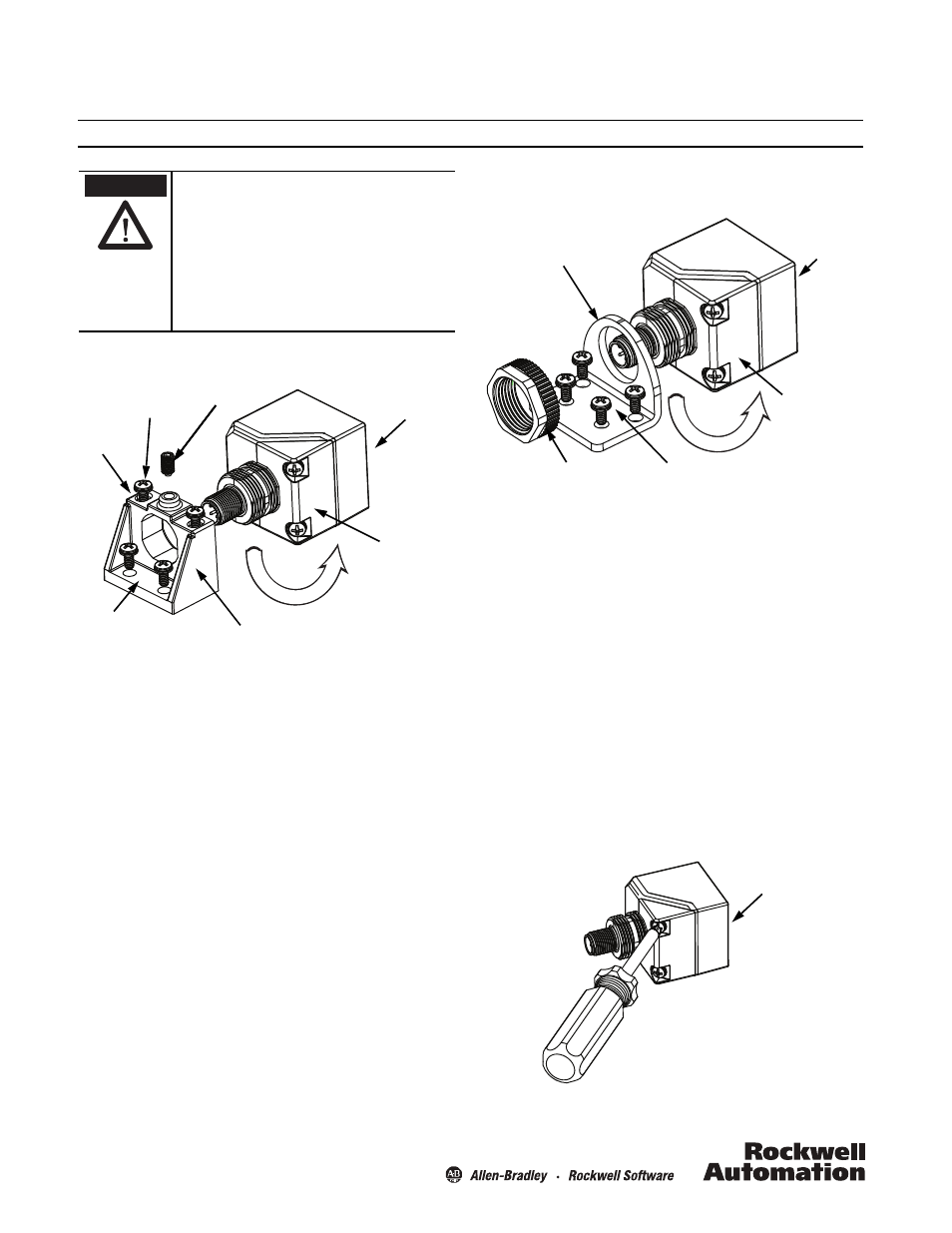
Mounting and Adjustment with the Zinc Bracket
Zinc Bracket Mounting
The VersaCube™ sensor and zinc bracket may come as a pre-
assembled unit.
Use either the slotted-hole mounting (A) or the through-hole
mounting (B). The slotted mounting holes allow fine adjustment
of sensing position by sliding the unit back and forth before
tightening the screws.
Follow these steps to install with the zinc bracket:
1. Mount the unit to a stable, flat surface using two screws (not
included). Recommended: 10-32 x 1.75 in. for slotted holes,
10-32 x 0.75 in. for through holes, or equivalent 5-mm screws.
2. Tighten the mounting screws to 0.9 N-m (8 in-lb), maximum.
Rotating the Sensor
1. Loosen the set screw with a 2.5-mm hex tool to remove the
sensor from the zinc bracket.
2. Rotate the sensor in 90-degree increments to the desired
orientation.
3. Insert the sensor back into the zinc bracket.
4. Tighten the set screw to 0.56 N-m (5 in-lb), maximum.
To change between top and side sensing positions, see
“Changing the Sensing Head Position,” at right.
Solid-state devices can be susceptible to radio frequency
interference (RFI) depending on the power and the
frequency of the transmitting source. If RF transmitting
equipment is to be used in the vicinity of the solid state
devices, thorough testing should be performed to assure that
the transmitter operation is restricted to a safe operating
distance from the control equipment and its wiring.
If a hazardous condition can result from unintended
operation of this device, access to the hazardous area should
be guarded.
ATTENTION
Set screw
Through-hole
mounting (B)
Zinc bracket
Slotted-hole
mounting (A)
Sensor face
45-degree
mounting base
Set screw
Set screw
Mounting screws
(not included)
Mounting with the Stainless Steel L-Bracket
(optional accessory)
Stainless Steel L-Bracket Mounting (optional)
1. Insert the sensor into the optional L-bracket in the desired
orientation.
2. Tighten the provided 22-mm plastic mounting nut to 0.9 N-m
(8 in-lb), maximum.
3. Mount the L-bracket to a stable, flat surface using at least two
screws (not included). Recommended: 10-32 x 0.75 in. or
equivalent 5-mm screws.
4. Tighten the mounting screws to 0.9 N-m (8 in-lb), maximum.
To change between top and side sensing positions, see
“Changing the Sensing Head Position,” below.
Changing the Sensing Head Position
To switch the sensing head between top and side sensing
positions, follow these steps:
1. Remove the sensor from the mounting bracket (zinc or
L-bracket).
Stainless steel L-bracket
(optional accessory)
22 mm plastic
mounting nut
Sensor face
45-degree
mounting base
Mounting screws
(not included)
Sensor face