Rockwell Automation 440F Safedge Pressure Sensitive Safety Edge System User Manual
Page 9
6.0 MAINTENANCE AND SERVICE
6.1 FAULT FINDING GUIDE
Symptom
Probable Cause
Check
“Yellow” LED
Open circuit in profile or
Z1-Z2 Terminals are secure.
Illuminates.
connecting wiring.
Cable for breaks
Profile for damage.
No LED’s illuminate even if
Supply failure.
Voltage selector switch is set correctly.
Profile is pressed.
Supply fuse.
Supply voltage is present.
No LED’s illuminate unless
Failure to reset.
If using contactor monitoring, check
Profile is pressed and then
each contactor is functioning correctly.
the stop “Red” LED
MC-MC terminals are secure.
illuminates.
Link is in place or Reset button
functions correctly.
Unit appears to work
Blown fuse.
Output fuses.
correctly but there is no
Damaged or incorrect wiring.
All wiring for damage.
output.
Fault on Safedge causing
Movement on any internal relays.
the Outputs to fail safe
REPLACE CONTROLLER.
Machine does not stop if
Incorrect external connections
All wiring to contactors for mistakes.
Profile pressed.
Run “Green” LED goes off.
Machine does not stop if
DO NOT ALLOW THE USE OF THE MACHINE
Profile pressed.
REPLACE CONTROLLER.
Run “Green” LED stays on.
6.2 MAINTENANCE
This section should be read in full before any maintenance work is attempted.
Attention is drawn to regulations for planned preventative maintenance under E.U. Directive
89/655/EEC (Implemented in Great Britain as the Provision and Use of Work Equipment Regulations
1992).
During maintenance operations, disconnect the machine’s prime mover before working on the
Safedge system. Observe electrical safety precautions.
19
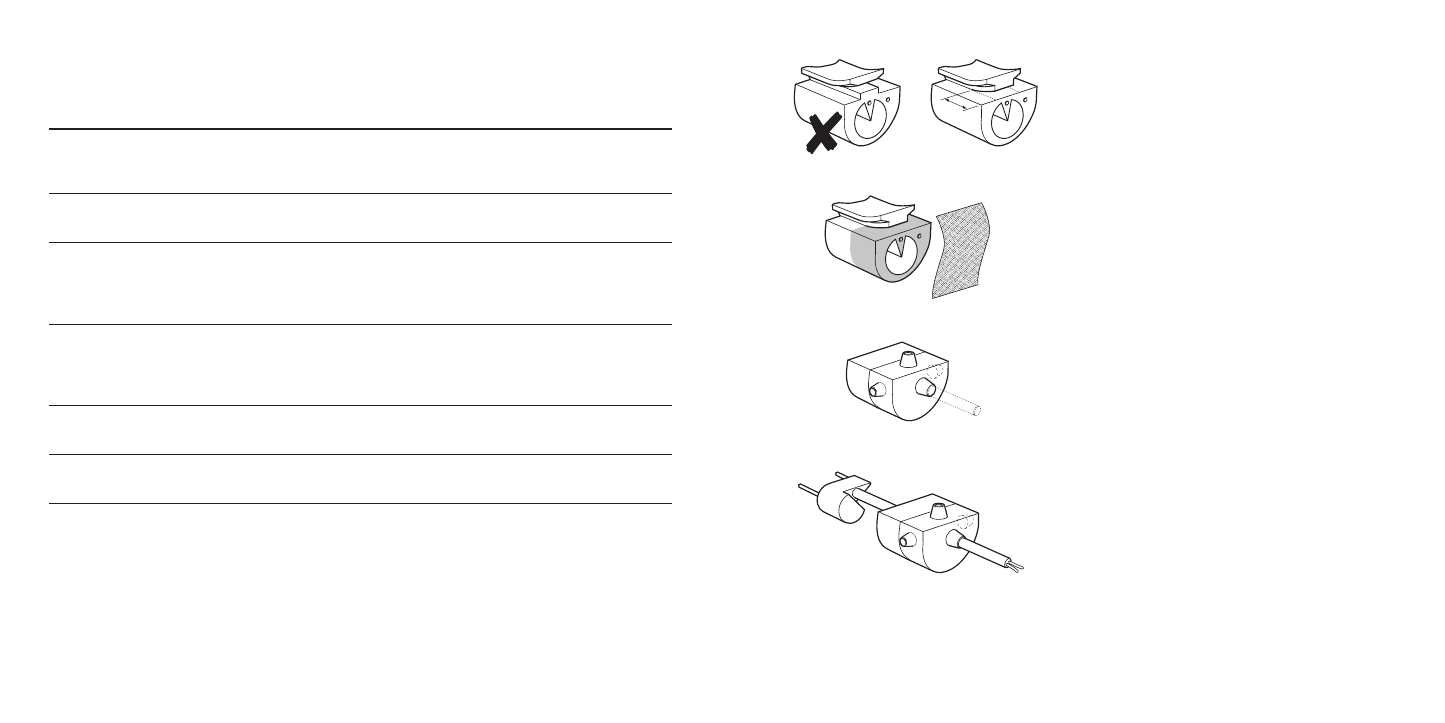
3.2.2 When using the closing cap 440F-A1302 with
sealing lip, the profile base has to be cut
back to a length of 12mm. The cut must
be made carefully to ensure that the profile
base is completely trimmed off, leaving a
flush surface.
3.2.3 The shaded areas must be roughened
with emery paper
3.2.4 The closing caps are moulded with 4
grommets, each with a rubber plug. When
fitting a resistor, leave the plugs intact. When
making a cable connection, select the
required cable exit and remove the plug from
the grommet with a hole punch.
3.2.5 Pull the connecting cable through the
hole.
12
8