Rockwell Automation 844C Incremental Encoder User Manual
Page 2
Publication 75008–133–01(B)
Document 910 990 103 489
February 2000
Printed in USA
Visit our web site at:
http://www.ab.com/sensors
Mounting Instructions
IMPORTANT: Be sure the mating shaft meets the
tolerance requirements shown in the tables in the
Dimensions section.
IMPORTANT: Be sure mating shaft is chamfered and
grease-free.
1. Loosen the screw on the clamping ring with the 2.5mm
hexagon socket wrench.
2. Slide the encoder onto the mating shaft until the flex mount
rests on the machine surface.
The encoder should slide freely onto the shaft; if not, do
not force. Check the shaft for interferences such as
gouges, burrs, rust or size.
If mounting holes already exist, proceed to Step 6.
3. Hold encoder firmly and mark the four mounting holes.
4. Slide the encoder off. Drill and tap the marked holes to
accept M4 (or equivalent) screws.
5. Slide the encoder back onto the shaft until the flex mount
rests on the machine surface.
6. Attach the encoder with four M4 (or equivalent) screws.
IMPORTANT: Do not stress the flex mount while
tightening the screws.
7. Tighten the clamping ring screw to 1.1 Nm (10 in–lbs).
8. Make the electrical connections according to the table
under Electrical Connections.
IMPORTANT: Wiring must be in accordance with the
National Electric Code and applicable local codes and
ordinances.
9. Apply the specified voltage.
Electrical Connections
Function
Line Driver
Wire Color
Open Collector
Wire Color
V DC
Red
Red
Common
Blue
Blue
A Output
White
White
B Output
Pink
Pink
Z Output
Violet
Violet
A Output
Brown
NC
B Output
Black
NC
Z Output
Yellow
NC
Shield
Drain Wire
Drain Wire
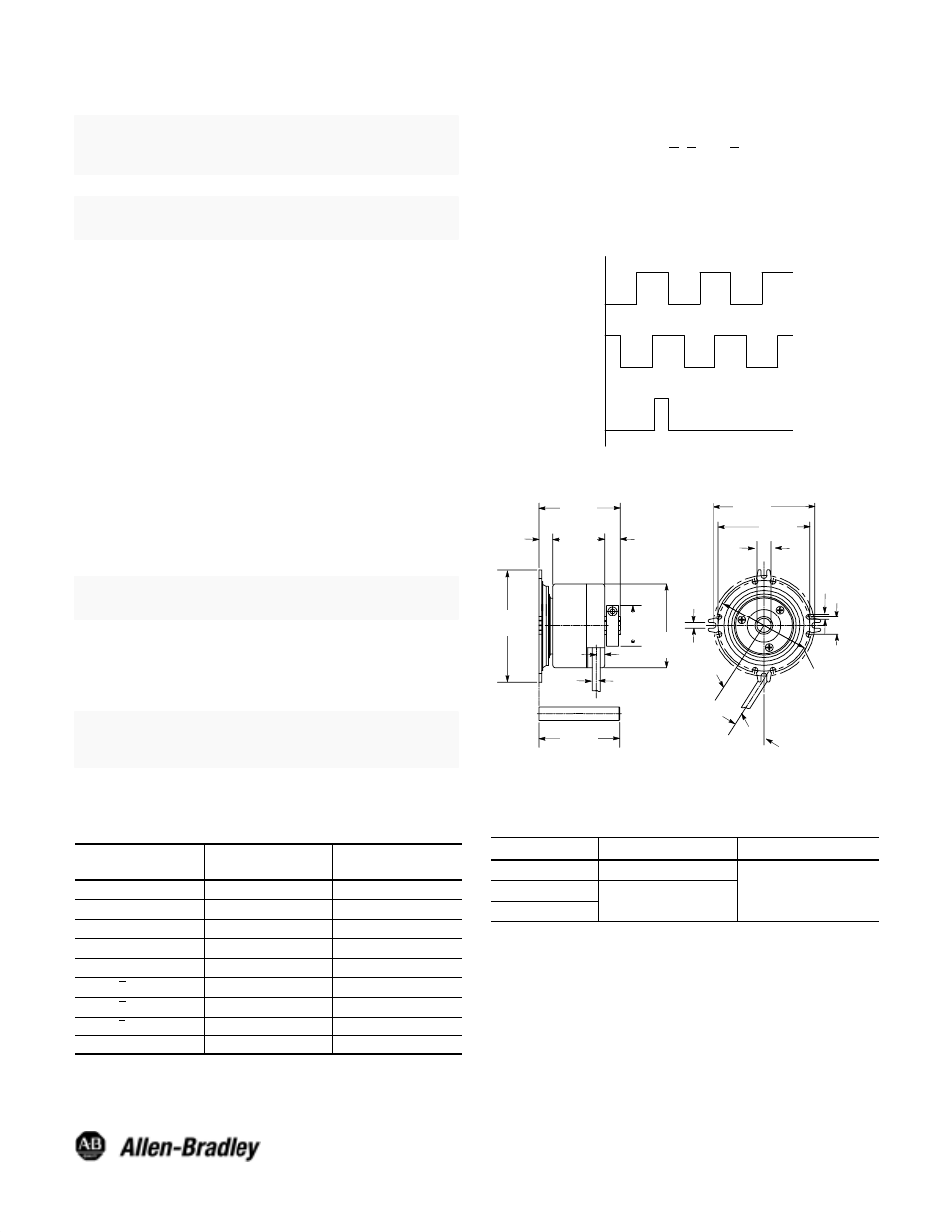
Output Waveforms
1. Channel A leads Channel B for clockwise rotation when
viewed from face of the encoder.
2. Complementary signals (A, B, and Z) are supplied only on
units with line drivers.
3. Marker Pulse is 1/4 cycle and is gated on the positive-
going edge of Channel B for clockwise rotation.
A
B
Z
Channel
Dimensions—mm
68
(2.68)
DIM
X"
12
(0.47)
4.2
(0.17)
32.5_
20.4
(9.80)
∅
29.5
(1.16)
6
(0.24)
11
(0.43)
9.8
(0.37)
Bulletin 844C
57.8
(2.28)
37
(1.46)
80.8
(3.18)
57
(2.24)
min
∅
5.5
(0.22)
∅
60
(2.36)
3.4
(0.13)
65
(2.56)
72
(2.84)
844C Mating Shaft Tolerance—mm (inches)
Bore
Diameter
Length
6mm to 10mm
+0.0/-0.015 (+0.0/-0.0006)
3/8I
0 0/ 0 018 ( 0 0/ 0 0007)
11.0/25.0 (0.433/0.984)
1/2I
+0.0/-0.018 (+0.0/-0.0007)
11.0/25.0 (0.433/0.984)