Safety plc program – Rockwell Automation 284G ArmorStart - Safety Version - Getting Started User Manual
Page 7
Publication 284GS-QS001A-EN-P - May 2009
7
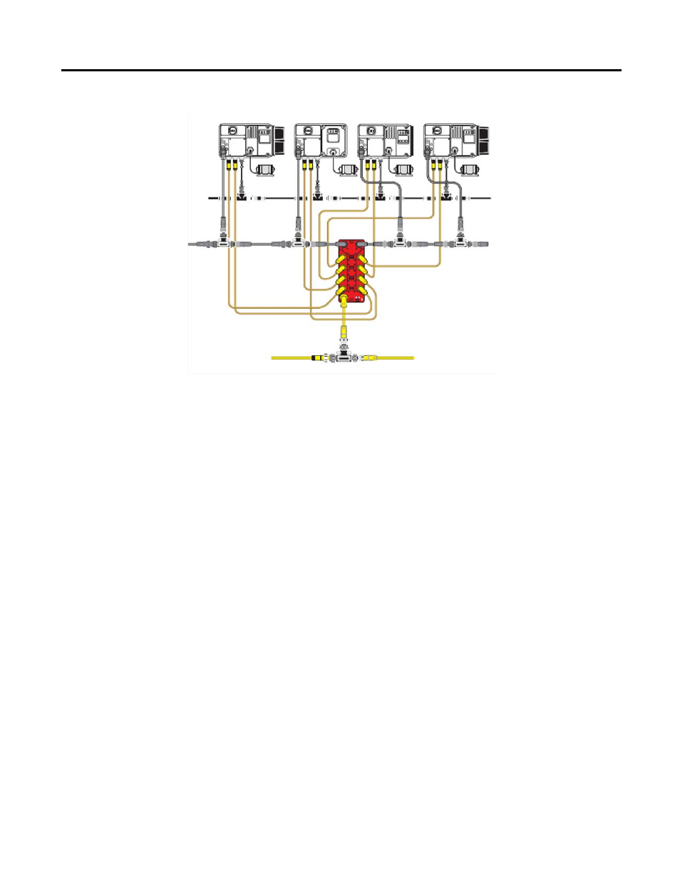
Figure 6 Safety System Overview
Configuration of the
1732DS-IBXOBV4 Safety I/O
Note: To comply with T
Ü
V, the 1732DS-IBXOBV4 Safety I/O module
must be configured as indicated below:
Configure the output that is connected to the I/O output cable assembly for:
•
Dual (bipolar mode)
•
Safety Pulse Test
Configure the input that is connected to the I/O Input cable assembly as
follows:
•
Channel = Single
•
Mode = Pulsed Test Input from test output X
•
Source = Pulsed output from X
Safety PLC Program
The program must:
•
Force the output contactors to the open state when a safety-related stop
is demanded.
•
Force the output contactors to remain in the open state if the SM
feedback is open after a safety-related stop is executed (see Notes).
Note: The program must inhibit the contactor closure to satisfy safety
Category 4 of 13849-1.
Note: The SM feedback logic should be implemented only after a
safety-related stop for the Bulletin 284G controllers. It should be
ignored during normal operation. One of the series contactors is
used for the normal stop/start function for these controllers.
Therefore, a malfunctioning contactor circuit cannot be
distinguished from a normal running state.
DeviceNet Media
I/O input
I/O output
Aux. Power
Three-Phase Power Media
The 1732DS Safety I/O module outputs to
provided 24V DC power for control power
to the ArmorStart - A1/A2 control power
The 1732DS Safety I/O module inputs will monitor the status of the safety-rated contactors inside the ArmorStart -SM safety monitor input.
input