Wiring, Terminal designations, Power, control, and ground wiring – Rockwell Automation 284G ArmorStart - Safety Version - Getting Started User Manual
Page 4
4
Publication 284GS-QS001A-EN-P - May 2009
Wiring
Power, Control, and Ground Wiring
Table 1 provides the power, control, safety monitor inputs, and ground wire
capacity and the tightening torque requirements. The power, control, and
ground terminals will accept a maximum of two wires per terminal.
Table 1
Power, Control, Ground Wire Size, and Torque Specifications
Terminal Designations
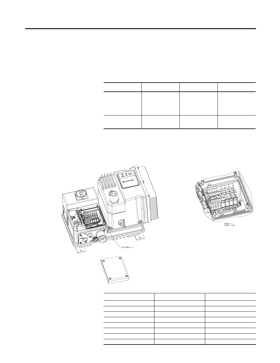
As shown in Figure 3, the ArmorStart Distributed Motor Controller contains
terminals for power, control, safety monitor inputs, and ground wiring.
Access can be gained by removing the terminal access cover plate.
Figure 3 ArmorStart Power, Control, Safety Monitor Inputs, and Ground Terminals
Table 2
Power, Control, Safety Monitor, and Ground Terminal Designations
Terminals
Wire Size
Torque
Wire Strip Length
Three-phase
Power
and
Ground
Primary/Secondary
Terminal:
1.5…4.0 mm
2
(#16 …#10 AWG)
Primary Terminal:
10.8 lb•in. (1.2 N•m)
Secondary Terminal:
4.5 lb•in (0.5 N•m)
0.35 in. (9 mm)
Control Power and
Safety Monitor Inputs
1.0 mm
2
…4.0 mm
2
(#18…#10 AWG)
6.2 lb•in
(0.7 N•m)
0.35 in. (9 mm)
Terminal Designations
No. of Poles
Description
SM1
2
Safety I/O Input
SM2
2
Safety I/O Input
A1 (+)
2
Control Power Input
A2 (-)
2
Control Power Common
PE
2
Ground
1/L1
2
Line Power Phase A
3/L3
2
Line Power Phase B
5/L5
2
Line Power Phase C