Rockwell Automation 845T Size 20 Incremental Encoder, Installation Instructions User Manual
Page 3
3
Electrical Connections
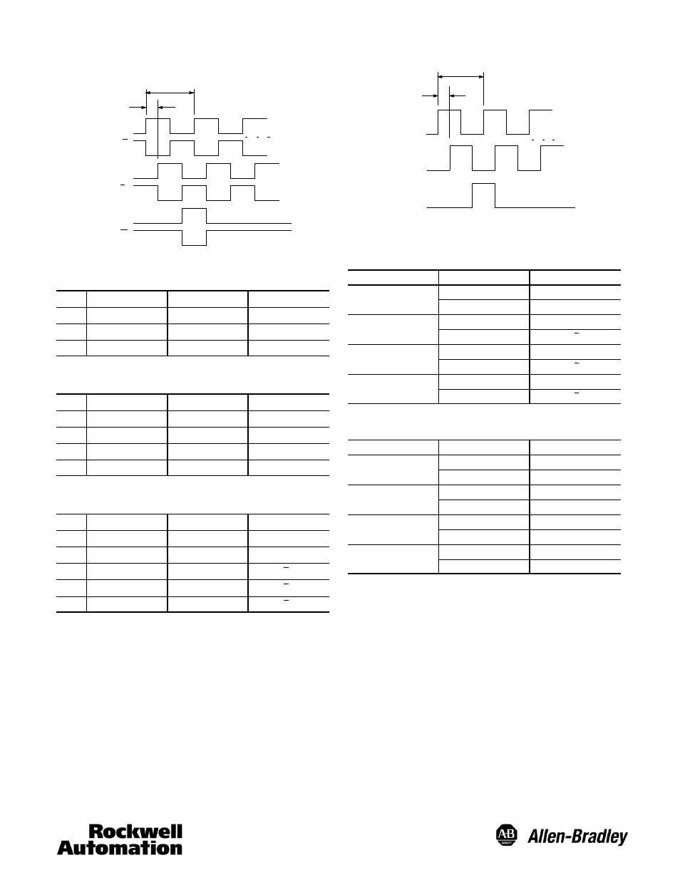
Differential Line Driver Output
Channel A
Channel A
Channel B*
Channel B*
(Index) Channel Z*
Channel Z*
Logic 1
Logic 0
(CCW Rotation Shown)
90 +/-- 22
°
1 Cycle
6-Pin Connector (ACS02E14S--6P (023))
Push-Pull Outputs
Pin
Function
Pin
Function
A
DC Return
D
Channel B Output
B
DC+ Input
E
Channel A Output
C
Channel Z Output
F
No Connection
7-Pin Connector (ACS02E16S--1P (023))
Push-Pull Outputs
Pin
Function
Pin
Function
A
Channel A Output
E
No Connection
B
Channel B Output
F
DC Return
C
Channel Z Output
G
No Connection
D
DC+ Input
—
No Connection
10-Pin Connector (ACS02E18S--1P (023))
Push-Pull, Differential Line Driver Outputs
Pin
Function
Pin
Function
A
Channel A Output
F
DC Return
B
Channel B Output
G
No Connection
C
Channel Z Output
H
Channel A Output
D
DC+ Input
I
Channel B Output
E
No Connection
J
Channel Z Output
Not included with push-pull outputs
Push-Pull Single End Driver Output
Channel A
Channel B*
(Index) Channel Z*
Logic 1
Logic 0
(CCW Rotation Shown)
* Optional Channels
90 +/-- 22
°
1 Cycle
Cable
Cable Differential Line Driver Outputs
Wire Pair
Wire Color
Function
Red/Black
Red
DC+ Input
Black
DC Return
White/Black
White
Channel A Output
Black
Channel A Output
Blue/Black
Blue
Channel B Output
Black
Channel B Output
Green/Black
Green
Channel Z Output
Black
Channel Z Output
Cable
Push-Pull Outputs
Wire Pair
Wire Color
Function
Red/Black
Red
DC+ Input
Black
DC Return
White/Black
White
Channel A Output
Black
Not Connected
Blue/Black
Blue
Channel B Output
Black
Not Connected
Green/Black
Green
Channel Z Output
Black
Not Connected