Rockwell Automation 845T Size 20 Incremental Encoder, Installation Instructions User Manual
Page 2
2
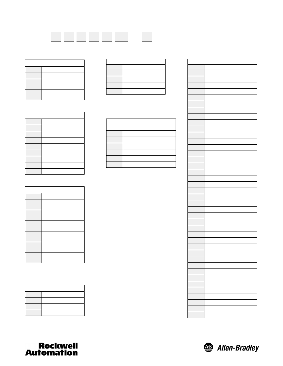
Selection Guide
845T — D
Z
1
3
E CR — C
a
b
c
d
e
f
g
a
Mounting Configuration
Code
Description
D
Square Flange
H
Servo with
Face Mount Holes
L
Servo without
Face Mount Holes
b
Shaft Options
Code
Description
A
6mm Diameter
B
10mm Diameter
C
1/4in Diameter
Z
3/8in Diameter
K
6mm w/Flat
L
10mm w/Flat
M
1/4in w/Flat
N
3/8in w/Flat
c
Electrical Options
Code
Description
1
5V DC in, 5V DC
DLD Out
2
5V DC in, 5V DC
P--P Out
3
11--24V DC in,
11--24V DC P--P Out
4
11--20V DC in,
5V DC DLD Out
5
24V DC in,
5V DC DLD Out
6
11--24V DC in,
11--24V DC DLD out
DLD = Differential Line Driver
P--P = Push-Pull Single Ended Driver
d
Signal Options
Code
Description
1
Channel A Only
2
Channel A and B
3
Channel A, B, and Z
e
Connection Options
Code
Description
A
6 Pin Connector
B
7 Pin Connector
E
10 Pin Connector
P
Pigtail Cable
This option not available with
Electrical Option codes: “1,” “4,” “5”
or “6.”
g
Mating Connector/Cable
Length
Code
Description
Blank
Without Mating Connector
C
With Mating Connector
1
1m (3.28ft) Cable Length
5
5m (16.4ft) Cable Length
9
9m (29.52ft) Cable Length
These options not available with Connection
Options code: “P.”
These options not available with Connection
Options code: “A,” “B,” & “E.”
f
Resolution
Code
Description (PPR)
AG
1
AM
5
BG
10
CA
50
CB
60
CE
64
CF
80
CG
100
DB
120
DF
150
EB
180
CH
200
CJ
250
CC
254
CW
256
EG
300
CK
360
CL
400
CM
500
DW
512
EH
600
DG
720
DL
800
LG
900
CN
1000
FW
1024
EL
1200
CD
1250
RF
1280
CU
1472
EM
1500
FL
1600
CP
1800
DN
2000
CS
2048
HL
2400
CR
2500
CY
2540
LJ
2750
EN
3000