Rockwell Automation 802PR Type LA and Type XA, Series C Installation Instructions User Manual
Page 2
802PR-IN002A-EN-P
77050-001-01
July 2013
Printed in Dominican Republic
PROGRAMMABLE OUTPUT SELECTION — The programmable
N.O./N.C. proximity switch is factory preset in either the normally
open or normally closed output mode.
To change the switch output mode use the following instructions.
1. Remove the lower legend plate on the front of the switch.
2. A line on the recessed rocker indicates the output mode of
the switch.
3. To change the output, depress the recessed rocker of the
switch with a pointed tool.
Note: Do not use a tool whose point could break and jam the
switch.
4. Replace the lower legend plate.
To return the output mode to its original setting, simply reverse
the above procedure. The OUTPUT LED will be ON when the
switch output is conducting.
HARD WIRED CONTACTS — When hard wired contacts are
connected in parallel with the Bulletin 802PR, a surge suppressor
MUST BE connected in parallel with the load. Surge suppression is
not required when hard wired contacts are connected in series
with the load. For recommended surge suppressors for various
devices, refer to publication 802PR-2.1 product data.
NOTE: Hard wired contacts that are operating in series or parallel
with the Bulletin 802PR Type LA or Type XA will cause a delay of
approximately 200 ms. This power-up delay will reduce the
maximum number of operations per minute and may result in a
momentary de-energization of the load.
CONDUIT COUPLED SWITCHES — Threaded conduit opening
bases are suitable for use with flexible conduit. Conduit coupler
bases are suitable for use with both flexible conduit and rigid
conduit. Both bases connect to 1/2 in.-14 NPT threaded conduit.
Switches with a “S6” suffix in their catalog number are suitable
for connection to ISO 20-1.5 threaded conduit.
PREWIRED CABLE SWITCHES — These switches include a
prewired cable for connection directly into a junction box. The
cable is a two conductor, oil resistant thermoplastic (STO).
PREWIRED RECEPTACLE SWITCHES — These switches include
a prewired receptacle suitable for use with the connector-cable
assemblies listed in the table below. Figure 6 indicates which two
pins of the receptacle are wired internally to terminals 1 and 2.
The third pin is not used.
Figure 6: End view of prewired receptacle
Connector Cable (supplied by user)
Manufacturer
Connector Cable Part Numbers
3-ft cable
6-ft cable
12-ft cable
Standard Color Code (green, black, white)
Brad Harrison
40901
40902
40903
Joy
X8984-3
8984-4
8984-5
CAM-LOK
E2057-624
E2057-625
E2057-626
Automotive Color Code (green, red, red)
Brad Harrison
40958
40959
40960
Joy
X8984-13
X8984-14
X8984-15
CAM-LOK
E2057-824
E2057-825
E2057-826
ATTENTION
Do NOT connect two or more Bulletin 802PR
switches in parallel. Erratic operation may
result.
Normally
closed
mode
Depress recessed rocker near
indicating line to change output mode
Normally
open
mode
Short Pin —
Connects to Terminal 1
Short Pin —
Connects to Terminal 2
Long Pin — Not used
TROUBLESHOOTING GUIDE — The following guide provides basic troubleshooting information for installation and use of the proximity
switch. If a problem occurs, attempt to determine the POSSIBLE CAUSE as listed. Apply the suggested SOLUTION.
NOTE: The switch may continue to operate even if the LED (will not light) is damaged.
Programmable N.O./N.C. switches have two LEDs. The POWER LED will be ON when power is applied.
N/A — Not Applicable.
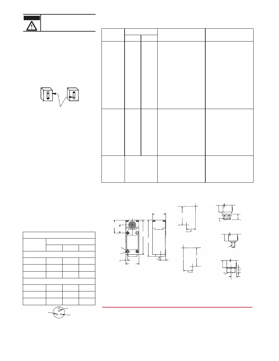
MOUNTING DIMENSIONS — Dimensions shown in mm (inches).
Symptom
Output LED
Possible Cause
Solution
N.O.
N.C.
Load will not
energize
OFF
OFF
A. Power supply off.
A. Apply power.
OFF
ON
B. Incorrect voltage applied
B. Apply correct voltage.
OFF
OFF
C. Broken wires or loose connections.
C. Repair wiring or tighten loose connections.
OFF
ON
D. Improper wiring.
D. Recheck connection diagrams. Rewire
accordingly.
OFF
N/A
E. Target too small or out of sensing range.
E. Increase target size of move target or switch
within sensing range.
N/A
OFF
F. Target or metal object within sensing range. F. Remove target or metal object. Refer to
EFFECTS OF NEARBY METAL SURFACES.
OFF
OFF
G. Two or more proximity switches placed too
close together.
G. Move sensing faces of switches apart. Refer
to SPACING BETWEEN SWITCHES.
ON
ON
H. Load device faulty or incorrect.
H. Replace load or size load correctly.
Load will not
de-energize
ON
N/A
A. Target or metal object within sensing range. A. Remove target or metal object. Refer to
EFFECTS OF NEARBY METAL SURFACES.
N/A
ON
B. Target too small or out of sensing range.
B. Increase target size of move target or switch
within sensing range.
ON
ON
C. Two or more proximity switches placed too
close together.
C. Move sensing faces of switches apart. Refer
to SPACING BETWEEN SWITCHES.
ON
OFF
D. Improper wiring.
D. Recheck connection diagrams. Rewire
accordingly.
OFF
OFF
E. Load device faulty or incorrect.
E. Replace load or size load correctly.
Load energizes and
de-engerizes
intermittently
ON & OFF intermittently
A. Broken wires or loose connections.
A. Repair wiring or tighten loose connections.
B. Target fluctuates in and out of sensing
range and hysteresis zone.
B. Stabilize target within the sensing range.
Refer to SPECIFICATIONS — Hysteresis.
C. Two or more proximity switches placed too
close together.
C. Move sensing faces of switches apart. Refer
to SPACING BETWEEN SWITCHES.
www.rockwellautomation.com
Americas: Rockwell Automation, 1201 South Second Street, Milwaukee, WI 53204-2496 USA, Tel: (1) 414.382.2000, Fax: (1) 414.382.4444
Europe/Middle East/Africa: Rockwell Automation NV, Pegasus Park, De Kleetlaan 12a, 1831 Diegem, Belgium, Tel: (32) 2 663 0600, Fax: (32) 2 663 0640
Asia Pacific: Rockwell Automation, Level 14, Core F, Cyberport 3, 100 Cyberport Road, Hong Kong, Tel: (852) 2887 4788, Fas: (852) 2508 1846
Power, Control and Information Solutions Headquarters
41
(1-5/8)
26
(1-1/84)
109
(4-11/32) 117
(4-5/8)
42
(1-21/32)
6 (15/84)
dia. holes
Front mounting
US (1-5/32 x 2-11/32)
DIN (30 x 60)
6 (15/84)
41
(1-5/8)
1/2 in.-14 NPT
Inside threads
Threaded Conduit Opening
15
(19/32)
(1-5/32)
(2-11/32)
Rear mounting hole pattern
front view
2 #10-32 tapped holes
9.5 (3/8) deep
30
(1-5/32)
60
(2-11/32)
Front mounting hole pattern
front view
2 holes for #10 or M5 screws
22
(13/16)
7/8 in.-16N
outside threads
Prewired cable
1 in. hub
1/2 in.-14 NPT
inside threads
15
(19/32)
Conduit Coupler
10 (13/32) dia.
16 AWG
2 conductor
STO cable
Prewired receptacle
16
(5/8)
Type LA only.
Also available with ISO 20-1.5 threads.