Rockwell Automation 802PR Type LA and Type XA, Series C Installation Instructions User Manual
Important: save these instructions for future use
Installation Instructions
Bulletin 802PR — Type LA and Type XA — Series C
IMPORTANT: SAVE THESE INSTRUCTIONS FOR FUTURE USE.
HAZARDOUS LOCATION SWITCHES — Switches for hazardous
locations meet Division 2; Class I Groups A, B, C, & D; Class II,
Groups F & G; and, Class III requirements. For additional
information refer to Publication GI-2.8 — A Summary of
National Electrical Code Requirements for Hazardous Locations.
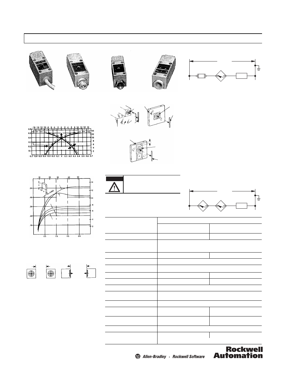
Figure 1: Typical sensing characteristics
Effects of Target Size and Materials on Sensing Distance
Figure 2: Typical sensing distance vs. target size for various metals
SPACING BETWEEN SWITCHES — When installing switches
side-by-side or face-to-face, the minimum spacings in Figure 3
should be maintained.
EFFECTS OF NEARBY METAL SURFACES ON SENSING
DISTANCES — The sensing distance will increase if the
proximity switch is installed so that metal is adjacent to the
sensing head surfaces as illustrated in Figure 4.
Prewired cable
Threaded conduit
opening
Prewired
receptacle
Conduit coupler
(Millimeters)
(Inches)
(Mi
llimeters)
Se
ns
in
g Distan
ce (in
ches)
Target
Release
Operate
Target
Square Target Size (x in Inches)
(Mi
llime
te
rs
)
Half Hard Cold
Aluminum (Alloy #1100-H14)
Cold Rolled Low Carbon
Cold Rolled
(Millimeters)
Head
O
n Se
ns
in
g Di
st
an
ce
(i
nc
he
s)
Stainless Steel (AISI 304)
Half Hard
Brass (Alloy 260 ASTM
Rolled Copper (ASTM-
Sensing Head Facing
Sensing Faces in Same Plane
3 in. minimum
2 in. minimum
Figure 4: Effects on nearby metal surfaces on sensing distances.
WIRING — Connect the proximity switch and load as shown in
Figure 5 using AWG #18 through #14 wire (1.0/1.5 mm
2
). The LED
of the switch will be ON when the load is energized.
SPECIFICATIONS
Description
Output Mode
Fixed
Normally Open
Programmable
Normally Open/Normally Closed
Operating voltage range
102…132V, 50/60 Hz
60…132V, 50/60 Hz
Load current
Max. continuous: 1 A to +40°C linearly derated to 0.5 A at +75°C
Max. inrush: 10 A, 1 second max.
Min.: 0.025 A
Max. leakage current (load off)
0.0065 A
0.0035 A
Max. voltage drop (load on)
7.5V
Operating temperature range
-25…+75°C (-13…+167°F)
Max. operate time
25 ms
25 ms
Max. release time
35 ms
25 ms
Delay on power-up target present
20 ms, typical (no output occurs with target absent)
Sensing distance
Steel: 0.525 in. +10% -5%. Refer to Figure 1
Nonferrous metals: 0.25 in. typical
Hysteresis (operate — release differential)
0.075 in. max.
Sensing distance drift with temperature
±5% 0…+75°C (32…167°F)
±10% -25…+75°C (-13…167°F)
±5% +15…+50°C (59…122°F)
±10% -25…+75°C (-13…167°F)
Max. sensing distance drift with voltage
±0.5% 102…132V
±1% 90…132V
±3% 60…132V
Repeat accuracy (10 successive operations)
0.001 in. max. deviation at constant temperature and supply voltage
Operating speed
(operations per minute)
1000
1200
Based on max. operate and release time
Sensing
Face
Metal
Sensing
Face
Target
Target
Target
Metal
Metal
Sensing
Face
D
D
D
1/4 in. Clearance
Figure 4a: Metal adjacent to one
side of head. Sensing distance D
increases approximately 2%.
Figure 4b: Metal surrounds head.
Sensing distance D increases
approximately 10%.
Figure 4c: Metal surrounds switch. Sensing
distance D increases approximately 8%.
WARNING
If a hazardous condition can result from
unintended energization of this device, access to
the sensing area should be guarded.
CONNECTION DIAGRAM
Figure 5: Typical wiring diagram
NOTE: To guard against the load remaining energized when the
switch is in an open condition, the minimum load release current
must be greater than the maximum leakage current of the
proximity switch.
GROUNDING — The Bulletin 802PR does not require a ground
connection. The load side of the110/120V AC source can be
grounded as indicated in the connection diagram.
SHORT CIRCUIT PROTECTION — A fuse is recommended in the
circuit to provide short circuit protection for the switch. Use a fast
acting Type KAW10 or KAX10 fuse.
SERIES CONNECTED SWITCHES —
Normally Open Fixed Output — Do not connect two or more
of the switches in series. Erratic operation may result.
Programmable Normally Open/Normally Closed Output
— Two switches can be connected in series with a load. For
proper operation, the operating load voltage must be less than or
equal to the minimum supply voltage less the sum of the on-
state voltage drops across the series connected proximity
switches. The load will be energized when the OUTPUT LEDs of
both proximity switches are ON.
CONNECTION DIAGRAM
Proximity
Switch
LOAD
Fuse
(if used)
(110/120V AC
L
1
L
2
LOAD
(110/120V AC
L
1
L
2