How to install a replacement coil – Rockwell Automation 500LG Coil Replacement Kits User Manual
Page 2
Installing Coil Replacement Kits 500LC–CCKA1, 2, 3, 4, 5 in Bulletin 500LC Lighting Contactors
2
Publication 500LC–IN002A–EN–P May 2005
How to Install a Replacement Coil
To avoid personal injury or property
damage, de–energize both line and control
power connected to the Bulletin 500LC
Lighting Contactor before proceeding.
CAUTION
1. Open circuit breakers, then use a voltmeter to verify no voltage is present at
both control and line terminal screws.
2. Label, disconnect, and tape all wires (control, line, load) from the lighting
contactor.
3. Loosen the mounting screws and remove the Bulletin 500LC Lighting
Contactor from the enclosure.
Disassembly
Coil assembly is mounted in center of the lighting contactor base. See Figure 1.
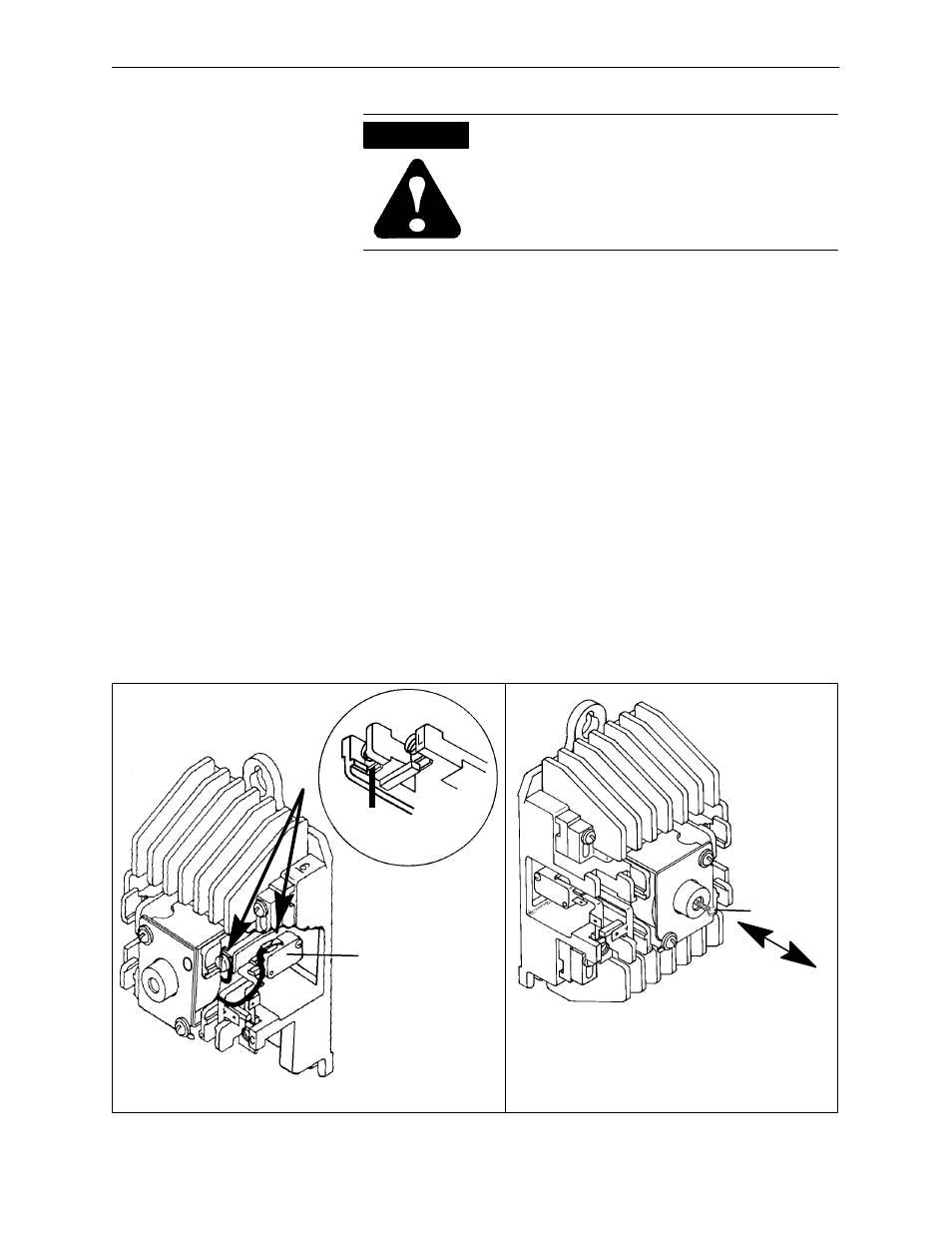
4. Disconnect the coil leads. Carefully pull the coil lead with the flag terminal off
the side of the miniature switch; the lug can be pushed from behind. Then
loosen the terminal screw closest to the coil to disconnect the other coil lead.
See Figure 2.
5. Remove the coil assembly. Use a screwdriver (counterclockwise) to remove
the two screws in the magnet frame. Then pull the coil assembly and
nameplate straight out.
Note: Leaf spring and actuator are loose parts on 2–...6–pole lighting
contactors. On lighting contactors with more than 6 poles the leaf spring is not
present, and the actuator is held in place by the lower contact block.
6. Remove the coil. Slide the coil out of the right side of the magnetic frame.
Figure 2 Coil Connections
manual
operating
screw
Figure 3 Manual operating screw
Do not manually operate
until all power and control
circuits are disconnected.
push — pull
connect coil
lead with flag
terminal to side
of miniature
switch
connect bare coil lead to
closest terminal screw
bare coil lead