Rockwell Automation 140U Q and M-Frame Circuit Breakers Installation of Q-Frame Circuit Breakers User Manual
Warning
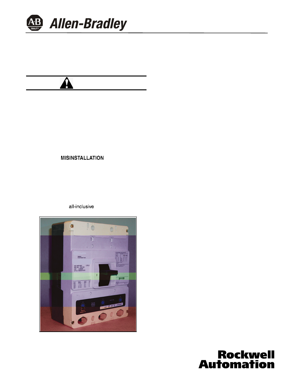
Q-Frame Circuit Breaker
Instruction Leaflet for Installation of Q-Frame Circuit Breakers
WARNING
CONTACT WITH ENERGIZED EQUIPMENT CAN
RESULT IN DEATH, SEVERE PERSONAL INJURY,
OR
SUBSTANTIAL PROPERTY DAMAGE. DO NOT
NANCE ON EQUIPMENT WHILE IT
IS ENERGIZED.
ALWAYS VERIFY THAT NO VOLTAGE
IS PRESENT
BEFORE PROCEEDING WITH THE TASK, AND
ALWAYS FOLLOW GENERALLY ACCEPTED SAFETY
PROCEDURES.
ATTEMPT TO INSTALL
OR PERFORM MAINTE-
ALLEN-BRADLEY
IS NOT LIABLE FOR THE MISAP-
PLICATION
OR
OF ITS
PRODUCTS.
The user is cautioned to observe all recommendations,
warnings, and cautions relating to the safety of personnel
and equipment as well as all general and local health and
safety laws, codes, and procedures. The recommenda-
tions and information contained herein are based on
Allen-Bradley experience and judgement, but should not
be considered to be
or covering every appli-
cation or circumstance which may arise. If any questions
Fig. 1-1 Q-Frame Circuit Breaker
Frame with Trip Unit Installed
arise, contact Allen-Bradley for further information or
instructions.
1.
INTRODUCTION
General Information
The Q-Frame circuit breaker (Fig. 1-1)
are 600 Vac maximum rated devices with
interchangeable thermal-magnetic or electronic
trip units rated 600A maximum continuous
current. The circuit breaker uses noninterchanageable
trip units and is factory sealed.
Refer to Table 1-1 for all available trip unit ratings.
This instruction leaflet (IL) gives procedures for installa-
tion and field testing of Q-Frame circuit breakers.
For this publication, the term circuit breaker shall also
include the molded case switch.
100 Percent Rated L-Frame Circuit Breakers
Q-Frame circuit breakers are suitable for conrtinuous
operation at 100 percent of the frame rating
if
used with 90°C insulated wire and AL9CU terminals in an
enclosure which measures at least 24" high x 15" wide x
6" deep. The minimum required ventilation is 8 sq. in. top
front and 8 sq. in. bottom front.
2.
INSTALLATION
The installation procedure consists of inspecting the cir-
cuit breaker and, as applicable, installing the trip unit and
rating plug, accessories, and terminals; mounting the cir-
cuit breaker; connecting the line and load conductors;
torquing terminals; and attaching terminal shields. Circuit
breaker frames, trip units, rating plugs, accessories,
mounting hardware, and unmounted terminals may be
Bul. 140U
40752-078(1)
Effective 5/02
supplied in separate packages. To install the circuit
breaker, perform the following steps.