Rockwell Automation 25B Bulletin 160 to PowerFlex 520-Series Adapter Plate User Manual
Page 2
Bulletin 160 to PowerFlex 520-Series Adapter Plate Installation
Publication 520-IN001C-EN-P - November 2013
Supersedes Publication 520-IN001B-EN-P - September 2013
Copyright © 2013 Rockwell Automation, Inc. All rights reserved.
Allen-Bradley, Rockwell Software, Rockwell Automation, Powerflex and TechConnect are trademarks of Rockwell Automation, Inc.
Trademarks not belonging to Rockwell Automation are property of their respective companies.
ww.ab.com/support/abdrives
4
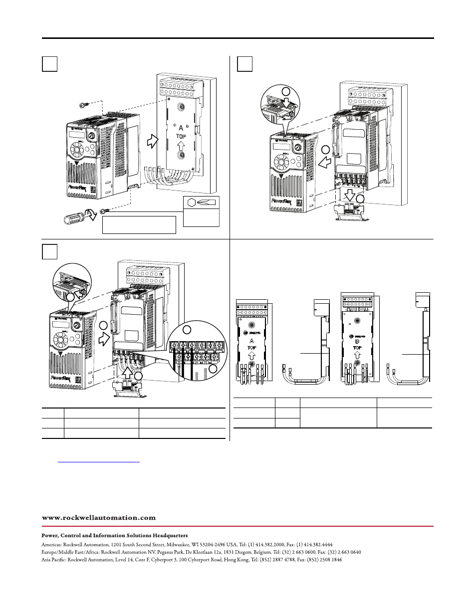
Install the PowerFlex 520-Series Drive
5
Separate the Control Module and Power Module
2 x M5
1.56...1.96 Nm
(14...17 lb-in)
M5
DC-
L1 L2 L3
BR+
DC+ BR-
Note: Four screws (supplied) are
required to mount Frame B.
a
Powerflex 520-Series Power Module Terminal Block Wiring
Frame
Wire Rating Min...Max
Torque
A
0.8...5.3 mm
2
(18...10 AWG)
1.76...2.16 Nm (15.6...19.1 lb-in)
B
2.1...8.4 mm
2
(14...8 AWG)
1.76...2.16 Nm (15.6...19.1 lb-in)
6
b
c
a
c
d
e
Frame A shown
Frame A shown
Wire the Adapter Plate to the Power Module
Frame A shown
Dimensions
All measurements are in mm (in.)
92.0 (3.62)
39.2 (1.54)
240.0 (9.45)
20.2 (0.80)
39.2 (1.54)
80.0 (3.15)
198.0 (7.80)
20.2 (0.80)
Bulletin 160 to PowerFlex 520-Series Adapter Plate Terminal Block Wiring
Catalog No.
Frame
Wire Rating Min...Max
Torque
25-MAP-FA
A
0.32...8.4 mm
2
(22...8 AWG)
1.59...1.94 Nm
(14.1...17.2 lb-in)
25-MAP-FB
B
Frame A
25-MAP-FA
Frame B
25-MAP-FB
b