Rockwell Automation 25B Bulletin 160 to PowerFlex 520-Series Adapter Plate User Manual
Installation instructions, Catalog numbers: 25-map-fa, 25-map-fb
Publication 520-IN001C-EN-P - November 2013
Installation Instructions
Bulletin 160 to PowerFlex 520-Series Adapter Plate
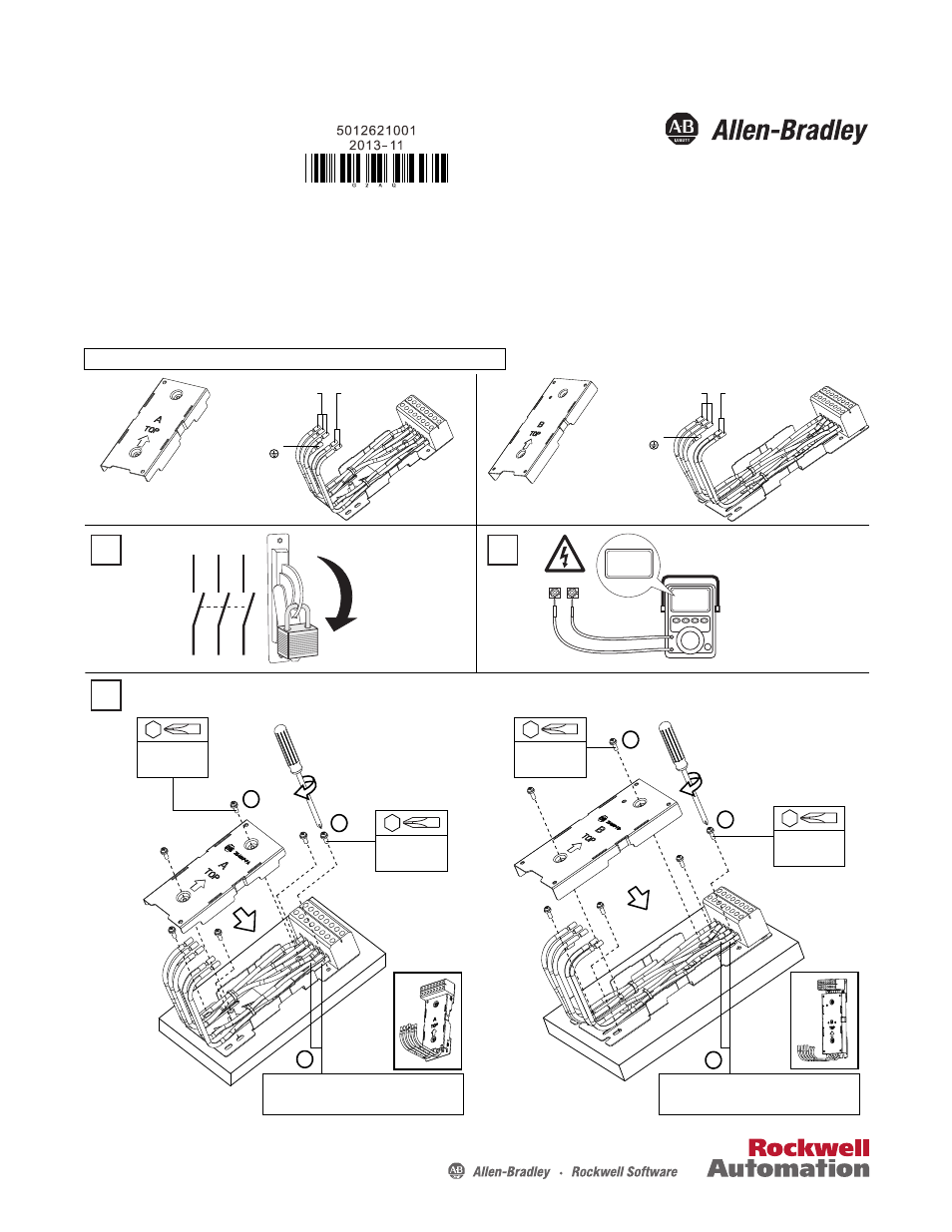
Installation
Catalog Numbers: 25-MAP-FA, 25-MAP-FB
Input power supply
(L1, L2, L3)
Protective
Earth ( )
Optional for braking
(BR+, BR-)
Input power supply
(L1, L2, L3)
Optional for braking
(BR+, BR-)
Protective
Earth ( )
Frame A
25-MAP-FA
Frame B
25-MAP-FB
L1
L2
L3
O
I
DC+ DC–
0V
0V
Wait three minutes
after shutdown for
capacitors to discharge
to safe voltage levels.
1
2
4 x M5
1.56...1.96 Nm
(14...17 lb-in)
M5
2 x M4
1.37...1.57 Nm
(12.15...14.8 lb-in)
M4
If no brake resistor is connected, detach the
BR+ and BR- wires from the terminal block.
3
Assemble the 25-MAP-FB Adapter Plate
Assemble the 25-MAP-FA Adapter Plate
4 x M4
1.37...1.57 Nm
(12.15...14.8 lb-in)
M4
2 x M4
1.37...1.57 Nm
(12.15...14.8 lb-in)
M4
If no brake resistor is connected, detach the
BR+ and BR- wires from the terminal block.
a
b
a
b
c
c
Series B design includes two additional wires for dynamic brake resistor connection (BR+, BR-).