Step 4 – Rockwell Automation 20-750-20COMM-F1 20-750-20COMM and 20-750-20COMM-F1 Communication Carrier Cards User Manual
Page 3
Rockwell Automation Publication 750COM-IN001E-EN-P - September 2012
3
20-750-20COMM and 20-750-20COMM-F1 Communication Carrier Cards
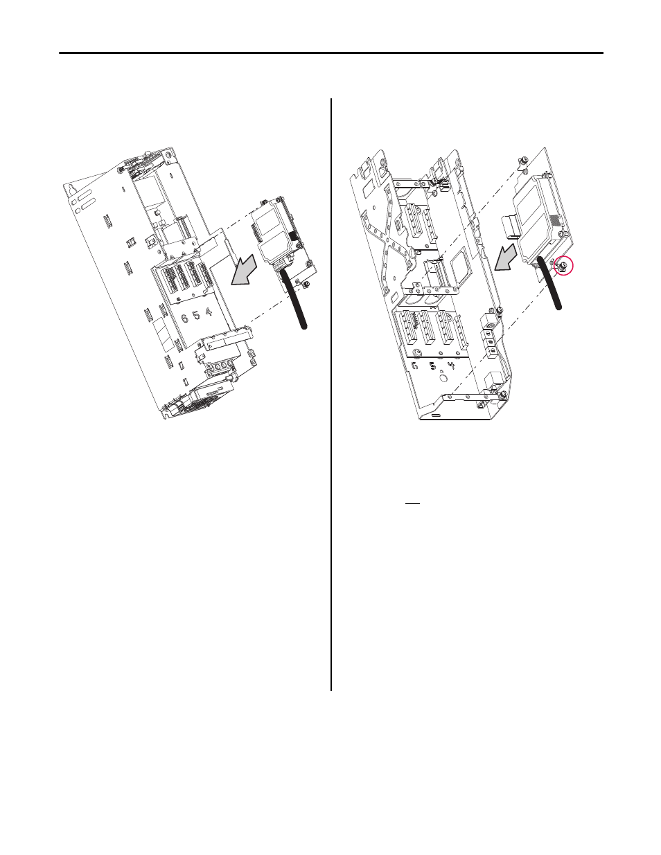
Step 4
20-750-20COMM Card
(for Frames 2 and higher
PowerFlex 750-Series Drives)
20-750-20COMM-F1 Card
(for Frame 1 only
PowerFlex 750-Series Drives)
DETAIL A
NOTE:
Port 6 is recommended. Installing the 20-750-20COMM Communication
Carrier Card into Port 4 or Port 5 will make the adjacent left port inaccessible
to other option modules, and may interfere with network cable connections.
For more details, contact Allen-Bradley Drives Technical Support.
Important: If a PowerFlex 20-750-PBUS Profibus option module resides in the
adjacent port to the right of the port in which the Communication Carrier Card is being
installed, the lower mounting screw of the Communication Carrier Card (shown in
DETAIL A above) may electrically contact the metal Profibus cable connector attached
to the Profibus option module. This may cause faulty operation. To prevent this,
perform steps 4-A through 4-C below. If a PowerFlex 20-750-PBUS Profibus option
module is not in that port, disregard these steps and proceed to step 5.
A. Remove the lower mounting screw, a T15 Torx head screw shown in DETAIL A
above, from the Communication Carrier Card.
B.
Replace the larger T15 Torx head screw with the smaller T8 Torx head mounting
screw that was shipped as a spare with the PowerFlex 20-750-PBUS Profibus
option module.
C.
Proceed to step 5.
TIP
To remove the captive T15 Torx head screw, the Communication
Carrier Card must removed to back the screw out of the mounting
clip.
NOTE:
Only install the 20-750-20COMM-F1 Communication Carrier Card in Port 4.
Do not install it in Port 5 or Port 6. Installing it into Port 4 will make the
adjacent left Port 5 inaccessible to other option modules, and may interfere
with network cable connections. For more details, contact Allen-Bradley
Drives Technical Support.