Warning – Rockwell Automation 140U N-Frame Circuti Breakers Instruction Leaflet for N-Frame Circuit Breakers User Manual
Page 9
40752-093(1)
Effective 5/02
Page 9
4.6 Ground Fault Pick-up Setting
Six settings marked 1x through 6x I
G
(where I
G
= 200
Amps) are available (see Fig. 4-4).
Note: These ampere values are always the same no
matter what rating plug is installed in the circuit
breaker.
4.7 Ground Fault Time Settings
Four flat settings (I,150,300,500 milliseconds) are avail-
able (see Fig. 4-4). The I setting gives a trip response
with no intentional delay (instantaneous).
5. GROUND FAULT CIRCUIT BREAKERS
BREAKER TRIP UNIT CAN BE DAMAGED BY HI-POT-
TING OR APPLYING EXTERNAL POWER TO ANY
COMBINATION OF THE YELLOW, GREEN, GRAY OR
WHITE LEADS. DAMAGE TO THE TRIP UNIT MAY
LEAD TO DEATH, SERIOUS PERSONAL INJURY, OR
PROPERTY DAMAGE. MAKE CONNECTIONS TO
THESE LEADS ONLY AS DIRECTED BY THIS
INSTRUCTION LEAFLET.
Ground Fault circuit breakers are supplied from the fac-
tory with one auxiliary switch with pigtail leads (red, blue
and black wires) and pigtail lead connections for a neutral
current sensor (white and grey wires) and a ground fault
alarm relay (yellow and green) wires, all installed in the
right pole of the trip unit. A neutral current sensor is pro-
vided with each trip unit. The ground fault alarm relay is
ordered and shipped separately if required.
WARNING
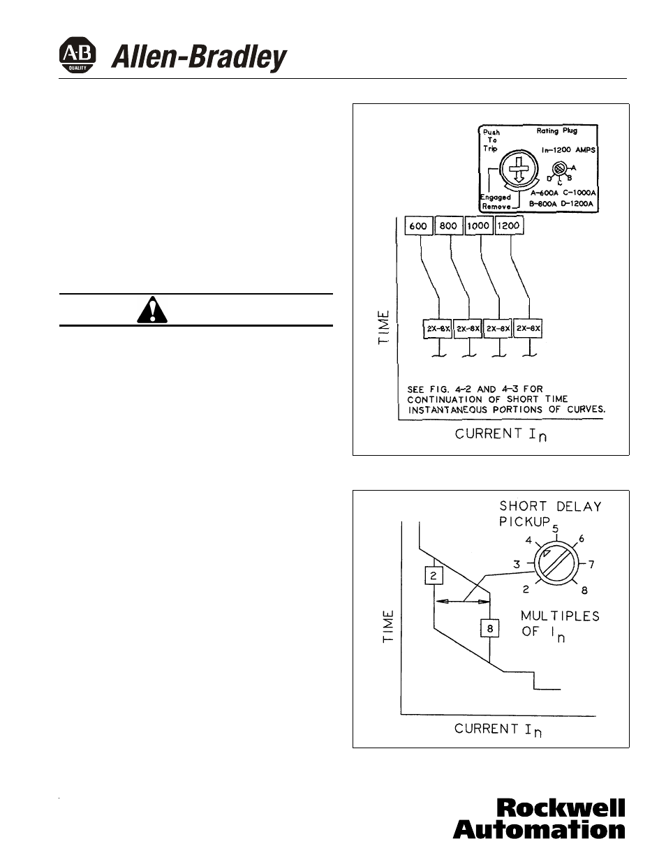
Fig. 4-1
Optional Adjustable Rating Plug
Fig. 4-2
Short Trip Current Adjustment and Curve
Details for L and G Type Trip units