Program lock password, Relay output contacts, Summary of parameter changes – Rockwell Automation 160 Series C Firmware User Manual
Page 6
6
160 Series C Custom Firmware
Program Lock Password
The S02 option provides a program lock feature with a three digit
integer (standard lock feature uses a single digit). All program group
parameters will be locked unless the correct integer is entered in P57 -
[Program Lock]. This parameter value will re-initialize to “000” or re-
lock whenever power is cycled. The program unlock will also be
required when using communication modules after the power is
cycled.
Relay Output Contacts
Parameters P47 - [Output Configure] and P48 - [Output Threshold] are not
used with the S02 option. Instead, the relay will function to indicate a
balanced condition after the balance test has been completed and to
indicate the braking mode until shut-off. A switching of the relay
contacts from the de-energized state will indicate a balanced
condition at the balance frequency or the braking mode.
Summary of Parameter
Changes
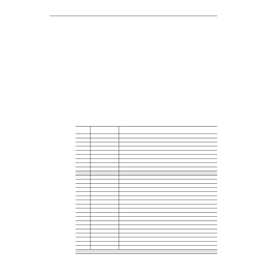
The following parameter changes have been made to the standard 160
Analog Signal Follower Drive.
Parameter
Number
Standard Analog
Drive Parameter Name What Changed?
20
New parameter
Smartspin Angle, see
“Smartspin Balance Detection” on page 3
30
Accel Time 1
Changed to Low Accel, see
“Accel/Decel Selection” on page 2
31
Decel Time 1
Changed to Low Decel, see
“Accel/Decel Selection” on page 2
38
Boost Select
Changed to Smartspin Level, see
“Smartspin Balance Detection” on page 3
41
Motor Overload Select
Changed to Balance Volts, see
“Smartspin Balance Detection” on page 3
43
Current Limit
Changed to Low Speed Current Limit, see
“High Speed Stall Prevention” on page 1
46
Input Mode
Min./Max./Default changed to 0/8/0
47
Output Configure
Changed to High Speed Current Limit, see
“High Speed Stall Prevention” on page 1
48
Output Threshold
Changed to DC Injection Current Limit, see
49
PWM Frequency
Min./Max./Default changed to 2.0/6.0/4.0
57
Program Lock
Min./Max./Default changed to 000/999/000 - see
“Program Lock Password” on page 6
62
New parameter
Smartspin Status, see
“Smartspin Balance Detection” on page 3
63
New parameter
Smartspin Time, see
“Smartspin Balance Detection” on page 3
64
New parameter
Smartspin Freq, see
“Smartspin Balance Detection” on page 3
65
New parameter
Smartspin Result, see
“Smartspin Balance Detection” on page 3
66
New parameter
Smartspin Scale, see
“Smartspin Balance Detection” on page 3
67
New parameter
Mid Accel - see
“Accel/Decel Selection” on page 2
68
New parameter
Mid Decel - see
“Accel/Decel Selection” on page 2
69
Accel Time 2
Changed to High Accel, see
“Accel/Decel Selection” on page 2
70
Decel Time 2
Changed to High Decel, see
“Accel/Decel Selection” on page 2
73
Reverse Disable
Changed to Low to Mid Crossover, see
“Accel/Decel Selection” on page 2
80
Stall Fault Time
Changed to Mid to High Crossover, see
“Accel/Decel Selection” on page 2
81
PI Proportional Gain
Changed to Start Frequency, see
“Five Point V/Hz Curve” on page 4
82
PI Integral Gain
Changed to Start Volts, see
“Five Point V/Hz Curve” on page 4
83
PI Process Reference
Changed to Breakpoint1 Frequency, see
“Five Point V/Hz Curve” on page 4
84
PI Dead Band
Changed to Breakpoint1 Volts, see
“Five Point V/Hz Curve” on page 4
85
New Parameter
Breakpoint2 Frequency, see
“Five Point V/Hz Curve” on page 4
86
New Parameter
Breakpoint2 Volts, see
“Five Point V/Hz Curve” on page 4
Shading indicates recent firmware changes