E-doc, S1 (msb) node address baud rate s2 (lsb) s3 – Rockwell Automation 800F- DeviceNet Push Button Stations User Manual
Page 2
41063-195
G. Ushakow
N/A
N/A
N/A
1007825
1
5-18-04
M. Jutz
5-18-04
B. Simon
5-18-04
2
2
REVISION
AUTHORIZATION
DIMENSIONS APPLY BEFORE
SURFACE TREATMENT
H
A
B
C
D
E
F
G
(DIMENSIONS IN INCHES)
TOLERANCES UNLESS
OTHERWISE SPECIFIED
REFERENCE
SHEET
OF
DWG.
SIZE
B
DR.
CHKD.
APPD.
DATE
DATE
DATE
ANGLES:
.XXX:
.XX:
THIS DRAWING IS THE PROPERTY OF
THE ALLEN-BRADLEY CO. INC.
AND MAY NOT BE COPIED, USED OR
DISCLOSED FOR ANY PURPOSE EXCEPT
AS AUTHORIZED IN WRITING BY
THE ALLEN-BRADLEY CO. INC.
LOCATION : MILWAUKEE,
WISCONSIN
U.S.A.
1
2
3
4
5
6
7
8
E-DOC
±
±
±
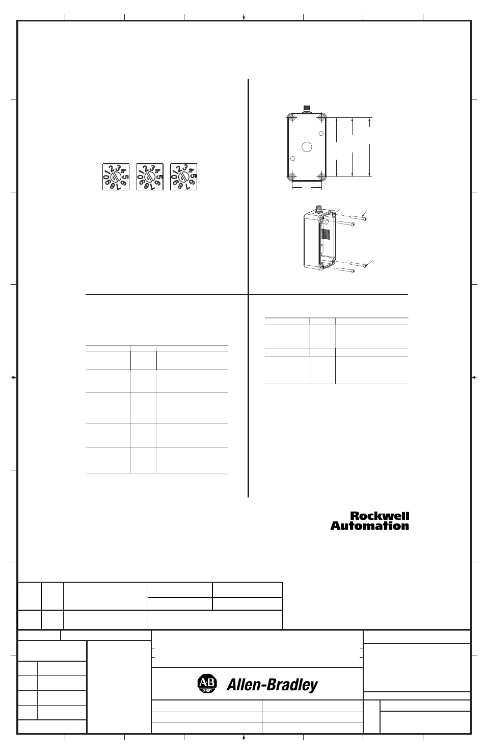
Set the Node Address
Valid node addresses are 00 to 63.
Set the node address using the rotary switches, RSNetWorx for DeviceNet
software, or another software configuration tool. Setting the switches
between 64 and 99 allows the software to have address control.
Each station is shipped with the node address set to 99. The switches are
located inside the enclosure on the circuit board. There are three switches
on the board. The Node Address switches are labeled as S1 MSB (most
significant byte) and S2 LSB (least significant byte).
To reset the node address, use a small blade screwdriver to rotate the
switches. Line up the small black triangle with the number setting you
wish to use. Then reset the unit via power or reset service.
Set the Baud Rate
This module is equipped with Autobaud detect. Autobaud lets the station
read the network data rate and automatically synchronize to it. If the user
wishes to hard set this data rate, the third rotary switch, S3, may be used.
For more information on the baud rate switch, please refer to the user
manual - 800-UM002A-EN-P.
Network and I/O Connections
This station uses 4 and 5 pin micro (12mm) style quick disconnect
connectors. The appropriate pinouts are shown on the product labeling.
If there are further questions, please refer to the user manual -
800-UM002A-EN-P.
Troubleshoot with the Indicators
The 800F Push Button Station has the following indicators:
• Mod/Net status indicator
•
•
•
•
•
•
•
•
Logic status indicator
The following table describes the mod/net status indicator.
Combined Module/Network Status LED
Mod/Net State
LED
Indication
Not Powered/Not
On-Line
Off
Device is not on-line.
The device has not completed the
Dup MAC ID test yet.
The device may not be powered yet.
Device Operational AND
On-Line, Connected
Solid Green
The device is operating in a normal
condition and the device is on-line with
connections in the established state.
For a Group 2 Only device it means
that the device is allocated to a master.
Device Operational AND
On-Line, Not Connected
Or
Device On-Line AND
Device needs
comissioning
Flashing
Green
The device is on-line with no connections
in the established state.
The device has passed the Dup MAC
ID test, is on-line, but has no established
connections to other nodes.
For a Group 2 Only device it means
that the device is not allocated to a master.
Minor Fault and/or
Connection Time-Out
Flashing Red
Recoverable fault and/or one or more I/O
connections are in the Timed-out state.
Recoverable faults include:
Failed Power Supply power-up test.
Faulted 24VDC, Out2, Out3.
Critical Fault or Critical
Link Failure
Solid Red
The device has an unrecoverable fault;
may need replacing.
The device has detected an error that
has rendered it incapable of communication
on the network (Dup MAC failure or bus-off).
The following table describes the logic status indicator.
Logic Status LED
Logic State
LED
Indication
DeviceLogix is NOT
Enabled
Off
Logic is disabled.
Note: Logic could be present on the device.
This LED only reflects whether or not it
is enabled.
DeviceLogix is Enabled Solid Green
Logic is enabled.
DeviceLogix is Enabled
and Forces Enabled
Flashing
Green
Forces are enabled.
Note: This implies that logic is also
enabled because outputs don't get forced
unless logic is enabled
DeviceLogix
This station is equipped with DeviceLogix, which allows it to run simple
and fast local logic. For more information on DeviceLogix configuration,
please refer to the 800F Push Button Station User Manual - 800-UM002A-EN-P
and the DeviceLogix User Manual - ACIG-UM001A-EN-P.
Mounting the Enclosure
Dimensions in inches (millimeters). Dimensions are not intended to be
used for manufacturing purposes.
S1 (MSB)
NODE ADDRESS
BAUD RATE
S2 (LSB)
S3
Sealed
Mounting Hole
10-32 (5mm)
Screws
Heads of screws must
be smaller than
3/8 inch to fit inside
mounting holes.
2 HOLE
4.7
(120mm)
3 HOLE
5.9
(150mm)
4 HOLE
8.3
(210mm)
2.4
(60mm)
DEVICENET
™
PUSH BUTTON STATION
BUL. 800F INSTRUCTION SHEET
TWO SIDED PRINTED,
BODY STOCK WHITE,
BODY INK BLACK
8-1/2" W x 11" H
4-1/4" W x 2-3/4" H
-01
FLAT
FOLDED
FINISHED SIZE
MATERIAL
CHG.
LTR.
PART
NO.
1
41063-195-01 (1)
Printed in U.S.A.