Rockwell Automation 598-NHL22M Hinge - Latch Installation User Manual
Page 3
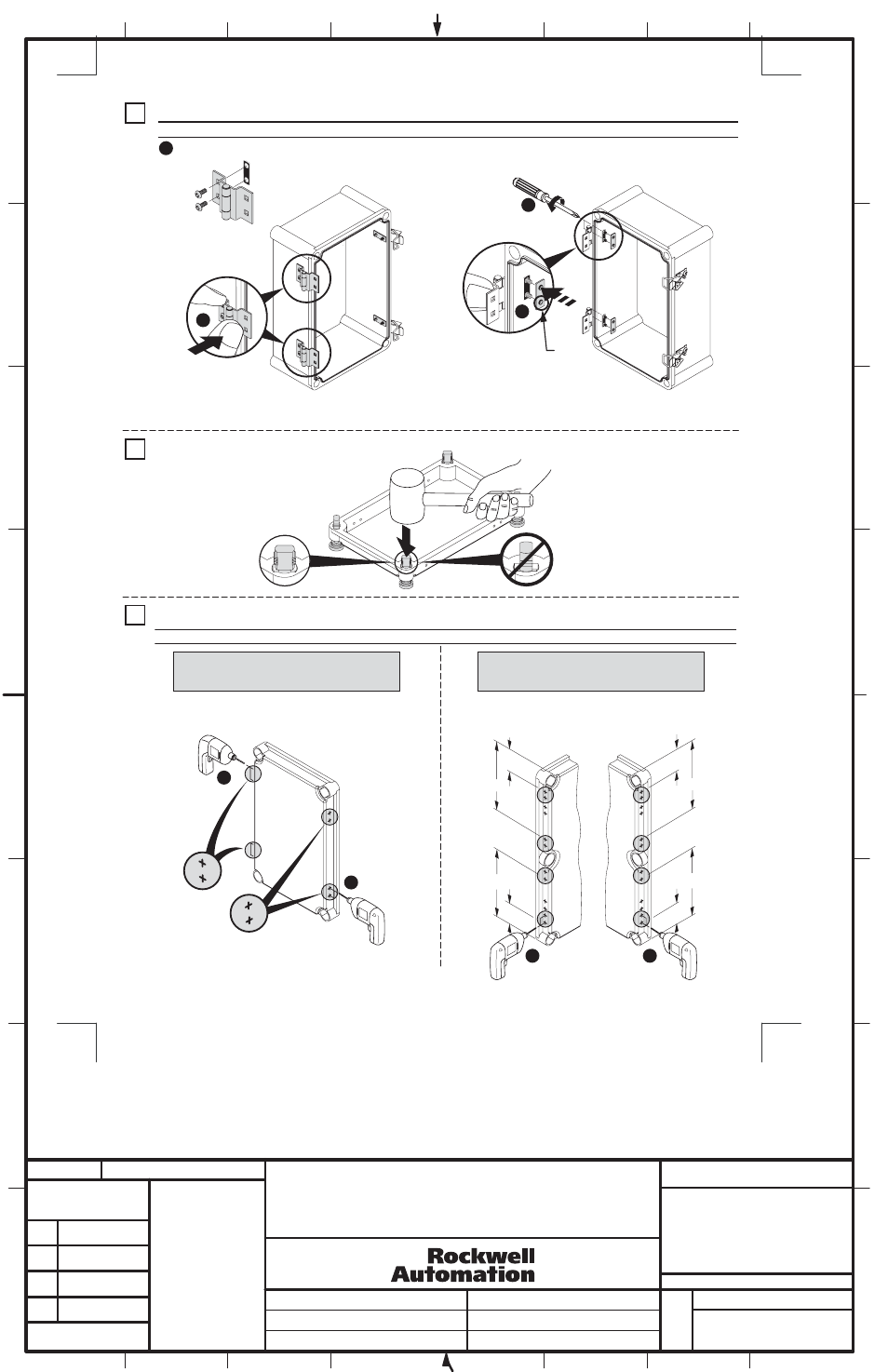
IMPORTANT: Each hinge assembly must have one gasket installed on each side of enclosure wall.
Hinge Installation
Drill Holes in Cover
2
1
Preassemble hinge, screws and gasket
3
5
Remove Captive Plastic Screws (If Present)
from Cover
4
2
1
4
6 - 12 lb-in
IMPORTANT: Drill bit diameter to not exceed .161 in (4.1 mm). Do not drill into the short sidess of the enclosure.
Note: Drill 1/16" pilot hole first, then drill 5/32" or
4mm hole for two latch hooks and two hinges.
Note: Drill 1/16" pilot hole first, then drill 5/32" or 4mm hole
for four latch hooks and four hinges in locations as circled in
diagram.
22" Long Enclosures
(598-BS22115_, -BS22157_)
7-1/2" thru 15" Long Enclosures
(598-BS885_ -BS1187_, -BS1587_, -BS11115_,
-BS13115_, -BS15117_)
2
1
9 in.
9 in.
2-1/2 in.
2-1/2 in.
2
2-1/2
in.
9 in.
2-1/2 in.
9 in.
Hinge Side
Latch Hook
Side
3
Extruded
side facing
away from
gasket
(3)
3
4
BULLETIN 598 HINGE-LATCH
INSTALLATION INSTRUCTION SHEET
1
1024601
42052-163
OF
N/A
N/A
N/A
REVISION
AUTHORIZATION
DR.
CHKD.
APPD.
DATE
DATE
DATE
E - DOC
LOCATION: MILWAUKEE, WISCONSIN U.S.A.
B-vertical.ai
DWG.
SIZE
SHEET
B
1
2
3
4
5
6
7
8
A
B
C
D
E
F
G
H
REFERENCE
DIMENSIONS APPLY BEFORE
SURFACE TREATMENT
(DIMENSIONS IN INCHES)
TOLERANCES UNLESS
OTHERWISE SPECIFIED
.XX:
.XXX:
ANGLES:
42052
THIS DRAWING IS THE PROPERTY OF
ROCKWELL AUTOMATION, INC.
OR ITS SUBSIDIARIES AND MAY NOT BE COPIED,
USED OR DISCLOSED FOR ANY PURPOSE
EXCEPT AS AUTHORIZED IN WRITING BY
ROCKWELL AUTOMATION, INC.
- - - - - - -
- - - - - - -
- - - - - - -
- - - - - - -
- - - - - - -
- - - - - - -