Maintenance, Actuation guidelines, Lever positioning – Rockwell Automation 440P Small Metal Safety Position Switches User Manual
Page 2: Torque specifications
2
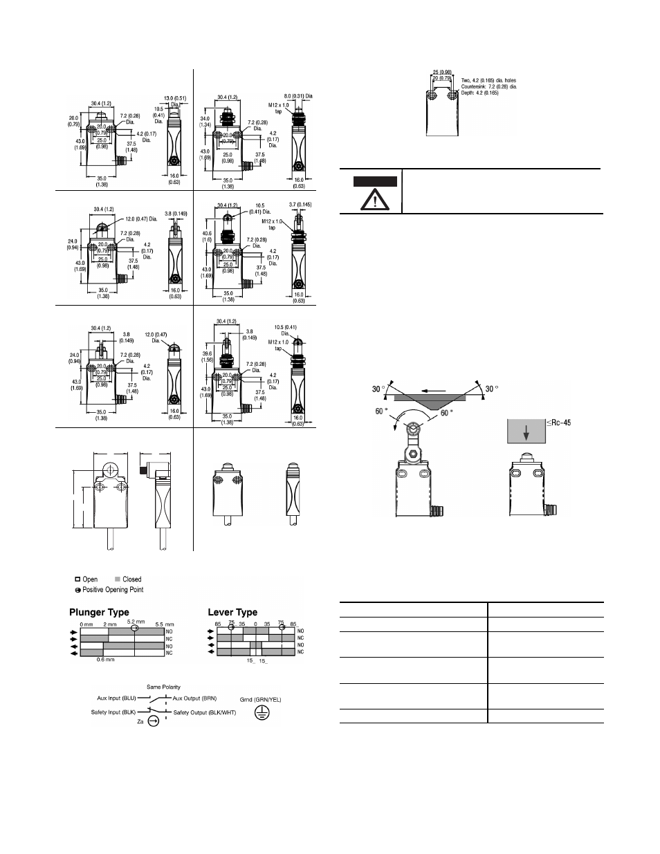
Mounting Dimensions [mm]
Contact Opening Characteristics
Wiring Diagram
Nonpanel Mount
Panel Mount
Dome
Plunger
Cross Roller Plunger
Bottom Cable Style
32.2
(1.27)
35.0
(1.37)
43.0
(1.69)
6.10
(2.40)
Replacement Switch, without
a Lever (440P-NX10)
Roller Plunger
Countersink Hole
\
• Panel mount clearance hole = 13 mm (0.51 in.) max.
Maintenance
These devices require little maintenance, but routine visual
inspection is recommended to keep foreign debris from
collecting on the exterior actuators and rollers. Removing the
operator head is not recommended as loose internal
components may be lost or improperly re-installed.
Actuation Guidelines
The method of actuation and over travel has significant
influence on the service life of the limit switch. To maximize
the service life, it is recommended to provide an actuator with
a 30° pressure angle and a surface hardness of Rc-45 max.
Lever Positioning
Some rotary switches are supplied with levers that are
mechanically coupled to the actuating shaft. The lever may be
removed and re-installed to adjust cam tracking. See table
below for torque recommendations.
Torque Specifications
Location
Torque
3.5 mm Operator Head Phillips Screws
0.8 N•m (7.1 lb•in)
Short and Wide Roller Lever A rm
8 mm Hex Nut
1.0 N•m (8.85 lb•in)
Adjustable Lever Arm
4 mm Allen Head Screw
1.8…2.8 N•m
(15.93…24.78 lb•in)
Adjustable Lever Arm Collar
3 mm Allen Head Screw
3.2 N•m (28.32 lb•in)
12 mm Panel Mount Nut
1.5 N•m (13.28 lb•in)
ATTENTION
Under no circumstances must the switch be actuated
beyond the mechanical travel specified. Serious
damage to the device and property could result.