Dr. date, Sheet size ver of 2 2 – Rockwell Automation 800H Potentiometer User Manual
Page 2
8. Rotate potentiometer clockwise to stop.
9. Place shaft adapter onto potentiometer shaft. Rotate shaft adapter to orient slot in shaft adapter with roll pin
in shaft while holes in diaphragm and mounting plate are in line with holes in mounting bushing.
10. Tighten the two set screws in the shaft adapter to 4 ± ½ lb.-in. with a 1/16" (1.6) hex wrench.
11. Line up holes in housing, mounting plate, and mounting bushing and push the unit into the mounting
bushing.
12. Secure by threading in the two screws from the rear of the potentiometer housing.
13. Rotate shaft counterclockwise to stop.
14. Position knob on shaft aligning white indexer on knob with "min." increment marking on legend plate.
15. Tighten the two set screws in the knob to 4 ± ½ lb.-in. with a 1/16" (1.6) hex wrench.
16. Install mounting ring and tighten. Allen-Bradley Catalog No. 800T-N3 wrench is available for this operation.
Enclosure must comply with U.L. standards 698 and 1203 and CSA standard C22.2 No. 30 for Class I
Groups B, C and D hazardous locations or C22.2 No. 25 for Class II Groups E, F and G hazardous locations.
For Class I locations, a suitable seal fitting is required within 18 inches.
Hole size to be .958 (24.3 Ø) to .970 diameter (24.6 Ø) ¾-14NPSM tap.
Apply grease from capsule (supplied) to threads of ¾-14NPSM hole before assembling units into panel and
to the threads of the lens assembly.
For standard length units (Bul. 800H), maximum panel
thickness is 1” (25.4). From 3/4” (9.5) to 23/32” (18.3)
securing ring is used as shown, without adjusting nut.
Securing ring is reversed when panel thickness is from
23/32” (18.3) to 29/32” (23) and eliminated between 29/32”
(23) and 1” (25.4).
For long barrel units (Bul. 800H), maximum panel thicknes
i s 2 1 / 2 ” ( 6 3 . 5 ) . F o r p a n e l s a b o v e 2 ” ( 5 0 . 8 ) b u t n o t
exceeding 21/2” (63.5) remove and discard securing ring
and tighten device with adjusting nut only.
For Class I Group B application, 5/8" (15.9) minimum
panel thickness is required.
Power Rating:
Maximum power (P) = 2 watts provided maximum working
voltage is not exceeded.
Maximum working voltage (EMAX) shall not exceed 300
volts (RMS or DC) or as determined by EMAX=
�PR, R =
resistance, whichever is less. See Table 1 for power
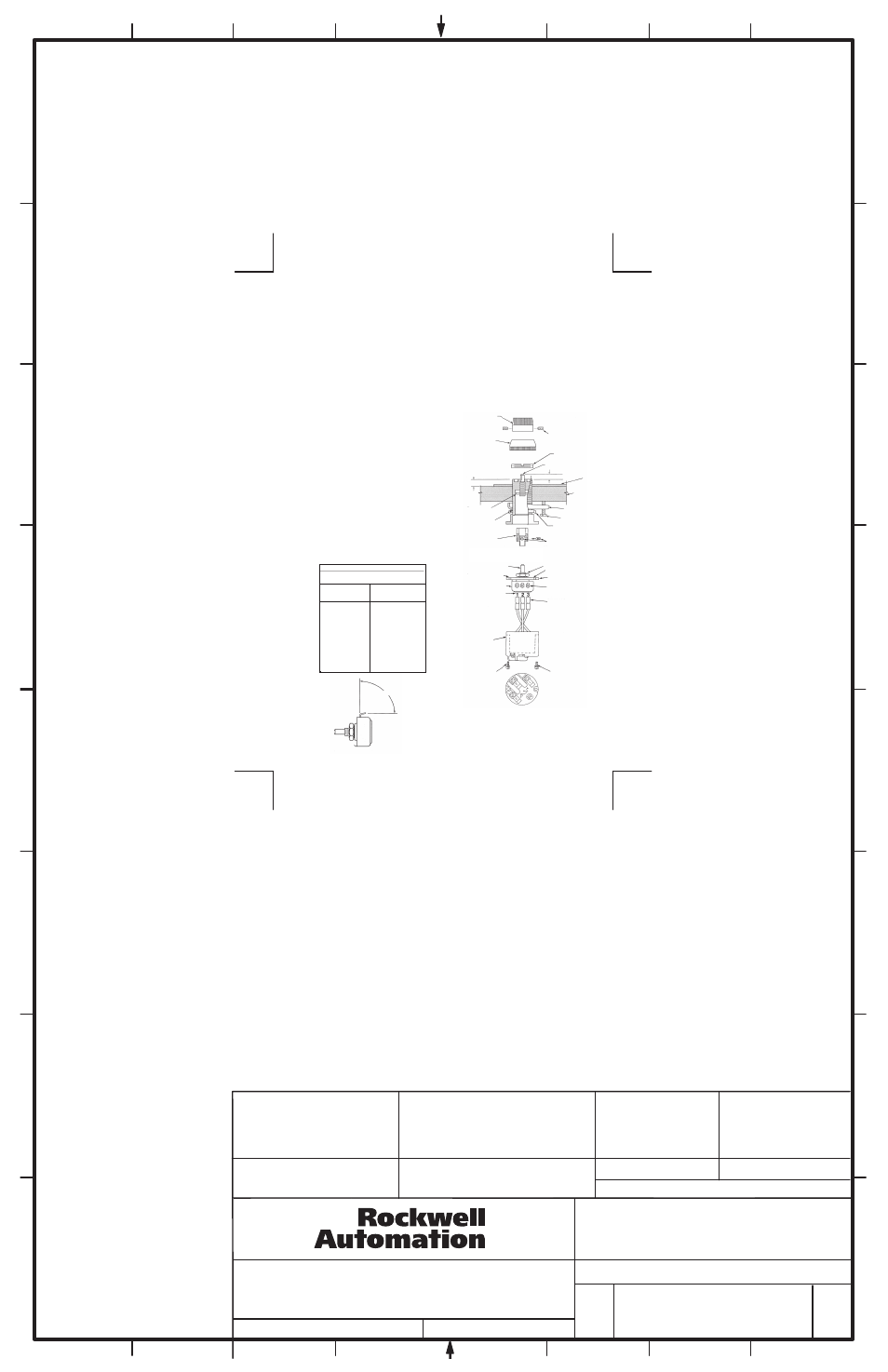
KNOB
ROLL PIN
MOUNTING
BUSHING
SHAFT ADAPTER
DIAPHRAGM
LOCATING TAB
POTENTIOMETER
TERMINAL
IDENTIFICATION
HOUSING
MOUNTING
SCREW
POTENTIOMETER SHAFT
SET SCREWS
1/16" (1.6) HEX WRENCH
TIGHTEN TO 4 ± 1/2 LB-IN
11/32 (8.7) IF
LEGEND PLATE
IS TO BE USED
9/32 (7.1) IF
LEGEND PLATE
IS NOT TO BE USED
SET SCREWS
1/16" (1.6) HEX WRENCH
TIGHTEN TO 4 ± 1/2 LB-IN
SHAFT
MOUNTING RING
ADAPTER
MOUNTING
RING
LEGEND
PLATE
LOCKING SCREW
ADJUSTING NUT
NUT AND LOCKWASHER
PRINTED SIDE
MOUNTING PLATE
POTENTIOMETER
TERMINAL
WIRE LEAD
MOUNTING
SCREW
NOTE:
WIRE RANGE:
18-14 AWG (0.5-2.5mm2)
TIGHTENING TORQUE:
6-7lb.in (0.7-0.8 Nm)
ENCLOSURE
SECURING RING
40 ± .01 (10.2 ± 2)
Table 1
Power derating with respect to rotation
for rheostat application
Percent
Rotation
Multiplying
Wattage
Rating By
100
1.00
90
.99
80
.98
70
.96
60
.93
50
.89
40
.81
30
.68
20
.49
10
.23
0
.11
80° - 90°
Figure 2
Figure 3
MATERIAL
NO.
MATERIAL
SIZE
FOLD
FLAT
4-1/4" W x 6-1/4" H 4-1/4" W x 3-1/8" H
TWO SIDES PRINTED
BODY STOCK WHITE
BODY INK BLACK
40060-303-01
B-vertical.ai
1
2
3
4
5
6
7
8
A
B
C
D
E
F
G
H
CONFIDENTIAL AND PROPRIETARY INFORMATION. THIS DOCUMENT
CONTAINS CONFIDENTIAL AND PROPRIETARY INFORMATION OF
ROCKWELL AUTOMATION, INC. AND MAY NOT BE USED, COPIED OR
DISCLOSED TO OTHERS, EXCEPT WITH THE AUTHORIZED WRITTEN
PERMISSION OF ROCKWELL AUTOMATION, INC.
40060-303
Sheet
Size
Ver
Of
2
2
B
05
Dr.
Date
- - - - - - - -
- - - - - - - -
40060-303-01 Ver (05)
Printed in U.S.A
�
INSTALLATION INSTRUCTIONS 800HL-EMP POTENTIOMETER
FOR NEMA TYPE 7 [3/8" (9.5) TO 2-1/2" (50.8) PANELS]
AND TYPE 9 [7/32" (7.2) TO 2-1/2" (50.8) PANELS]