Rockwell Automation 500LG Control Module Kit User Manual
Control module installation, Warning notice notice, E - doc
500LG
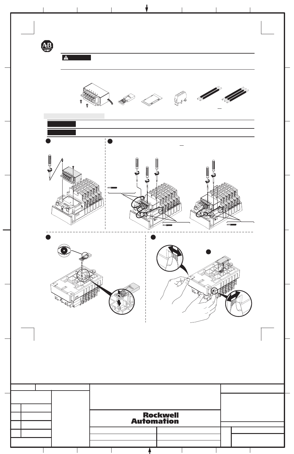
To prevent electrical shock, disconnect from power source before installing or servicing. Follow NFPA 70E requirements. Install
in a suitable enclosure. Keep free from contaminants.
Installation or removal of a control module kit to or from the Bulletin 500LG lighting contactor must be performed by a "Qualified
Person" as defined by the National Electrical Code.
The control module kits are designed for use with Bulletin 500LG lighting contactors only. Control module kits enable conversion of an
electrically held contactor to a mechanically held contactor. These kits are available in either 2-wire or 3-wire control versions in a variety of
voltages. The component parts of a 2-wire control module kit are shown. A 3-wire kit includes an additional single-pole auxiliary contact
block.
The control module kits are for use with the coils up to 277 VAC maximum. Use a control power transformer for higher voltages.
Latch and electronic module must be used together to ensure proper operation. Failure to do so will void warranty.
Control Module Kit for Bulletin 500LG Contactors
(Cat 500LG_)
Control Module Installation
Remove all packing material.
Mount the control module on the
contactor.
1
3
4
5
For 3-wire control, two auxiliary contact blocks
are assembled to the lighting contactor; one on
the right (N.C.) and one on the left (N.O.). Refer
to Table C on sheet 2 for connection diagram.
2
Mount the latch and be sure latch is firmly in place
with the wire facing out and the slot positioned with tab inserted.
Operate contactor manually, using manual operation tabs on side
prior to installing cover to ensure correct installation.
Install latch cover.
Operation Tab
500LG
500LG
5 lb-in
5 lb-in
7 - 12 lb-in
7 - 12 lb-in
7 - 12 lb-in
7 - 12 lb-in
#22 - #12 AWG
or
or
Control Module
Latch
Latch Cover
Auxiliary
2- Wire
Control
3- Wire
Control
(Stranded or Solid)
#22 - #12 AWG
(Stranded or Solid)
#22 - #12 AWG
(Stranded or Solid)
WARNING
NOTICE
NOTICE
For 2-wire control, one auxiliary contact block is
assembled to the right side of the lighting
contactor base for normally closed (N.C.). Two
wires coming from the control module are
connected across the auxiliary contact block.
Refer to Table A on sheet 2 for connection diagram.
1
2
BULLETIN 500LG
LIGHTING CONTACTOR CONTROL MODULE KIT
INSTRUCTION SHEET
1
1031018
42052-193
OF
N/A
N/A
N/A
REVISION
AUTHORIZATION
DR.
CHKD.
APPD.
DATE
DATE
DATE
E - DOC
LOCATION: MILWAUKEE, WISCONSIN U.S.A.
B-vertical.ai
DWG.
SIZE
SHEET
B
1
2
3
4
5
6
7
8
A
B
C
D
E
G
H
REFERENCE
DIMENSIONS APPLY BEFORE
SURFACE TREATMENT
(DIMENSIONS IN INCHES)
TOLERANCES UNLESS
OTHERWISE SPECIFIED
.XX:
.XXX:
ANGLES:
42052
G. Ushakow
2-21-08
2-21-08
2-21-08
M. Jutz
K. Vang
THIS DRAWING IS THE PROPERTY OF
ROCKWELL AUTOMATION, INC.
OR ITS SUBSIDIARIES AND MAY NOT BE COPIED,
USED OR DISCLOSED FOR ANY PURPOSE
EXCEPT AS AUTHORIZED IN WRITING BY
ROCKWELL AUTOMATION, INC.