Rockwell Automation 20-XCOMM-DC-BASE DPI External Comms Kit User Manual
Page 3
3
Configuring the Communications Adapter
After mounting and connecting the Comms Kit, configure
the communication adapter. Refer to the communication
adapter User Manual for complete details.
External Comms Kit Specifications
Communications
Electrical
Mechanical
Environmental
Regulatory Compliance
NOTE: In order to remain CE and CTick compliant, the
DPI cable length may not exceed 30 m (98.4 ft.).
NOTE: This is a product of category C3 according to IEC
61800-3. It is not intended for operation in a domestic
environment.
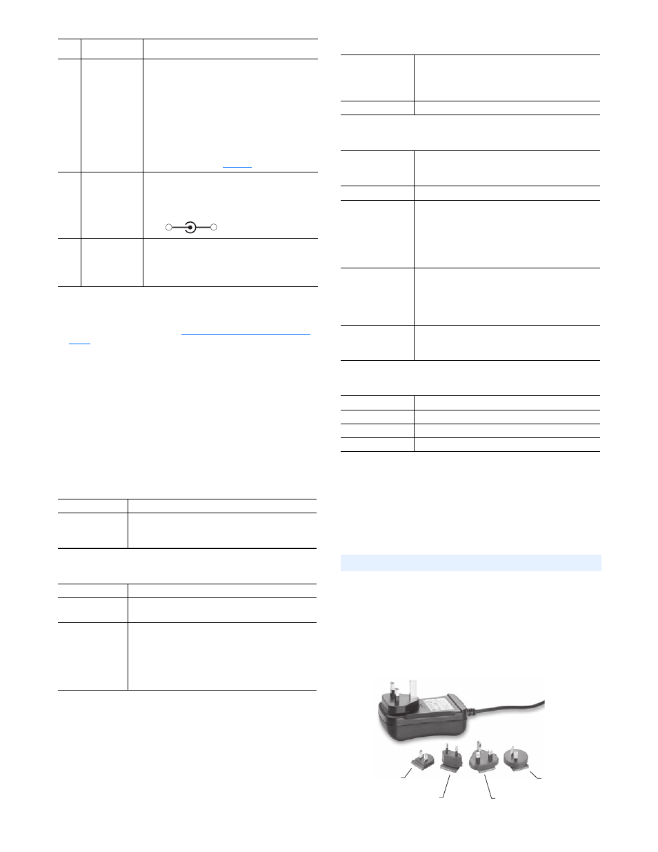
The 20-XCOMM-AC-PS1 is an accessory AC-to-DC
converter for use with the External Comms Kit. It is used
when only 100-240 VAC power is available inside a control
panel. The converter, which comes with interchangeable
plugs, is shown below. The converter connects to an AC
receptacle inside the control panel. Use the appropriate plug
for your region:
➌
24 VDC
Power Terminal
Block
(1)
Connection for 24 VDC (+15% / -25%) power
source. Connect the “ + ” and “ - ” wires of the
DC power source to the 2-pin linear plug
(provided with Comms Kit), matching the
respective polarity. Then insert the 2-pin linear
plug into the mating DC power terminal block.
NOTE: When powering the Comms Kit with the
accessory 20-XCOMM-AC-PS1 power adapter,
this terminal block can be used to daisy-chain
24 VDC to other kits (
).
➍
AC-to-DC
Adapter
Connector
(1)(2)
Connection for AC-to-DC adapter, such as
Allen-Bradley 20-XCOMM-AC-PS1, when not
using a DC power source. Plug the adapter into
the mating DC ADP connector.
➎
DPI Connector
Connection for DPI. Using a 1202-Cxx
Communications Cable, connect one end into the
mating DPI connector of the Comms Kit and the
other end into the port on the bottom of the drive.
(1)
The DC power source or AC-to-DC converter used to power the Comms Kit must
be capable of providing a minimum of 150 mA @ 18-27 VDC. Also, its connector
must be of “pin and barrel” construction with a 2 mm pin.
(2)
To power multiple Comms Kits, see
Powering Daisy-Chained Comms Kits on
.
Network
Dependent on installed 20-COMM-* adapter
Drive
Protocol
Data Rates
DPI
125 kbps or 500 kbps
Drive
60 mA at 12 VDC supplied from drive via DPI cable
Network
None for all network protocols except:
DeviceNet
60 mA at 24 VDC
DC Power Supply
Requirement
(1)
(1)
Since the Comms Kit is powered by a nominal 24 VDC, the current consumption
listed in this table differs from the value shown on the label of the communication
adapter, which is based on the adapter being powered by 5 VDC from the drive.
20-COMM-B
75 mA at 24 VDC
20-COMM-C
105 mA at 24 VDC
20-COMM-D
60 mA at 24 VDC
20-COMM-E
140 mA at 24 VDC
20-COMM-Q
135 mA at 24 VDC
20-COMM-M
140 mA at 24 VDC
Item Description
Connection Procedure
+
-
Dimensions
Width
Height
Depth
108 mm (4.25 in.)
108 mm (4.25 in.) with I/O terminal block attached
75 mm (2.95 in.)
Weight
340 g (12 oz.)
Temperature
Operating
Storage
-10 to 50
° (14 to 122° F)
-40 to 85
° (-40 to 185° F)
Relative Humidity
5 to 95% non-condensing
Atmosphere
Important: The Comms Kit must not be installed in
an area where the ambient atmosphere contains
volatile or corrosive gas, vapors or dust. If the
Comms Kit is not going to be installed for a period of
time, it must be stored in an area where it will not be
exposed to a corrosive atmosphere.
Shock
Operational
Non-operational
30g, 11 ms (DIN Rail Mount)
50g, 11 ms (Panel Mount)
30g, 11 ms (DIN Rail Mount)
50g, 11 ms (Panel Mount)
Vibration
Operational
Non-operational
2.5g, 5 to 2000 Hz
5.0g, 5 to 2000 Hz
UL
UL508C
CUL
CAN / CSA C22.2 No. 14-M91
CE
EN50178 and EN61800-3
CTick
EN61800-3
AC Power Adapter (20-XCOMM-AC-PS1)
For use in
the US
For use in
the UK
For use in
Europe
For use in
Australia