Rockwell Automation 20-XCOMM-DC-BASE DPI External Comms Kit User Manual
Page 2
2
Minimum Spacing
External Comms Kits can be zero-stacked (side-by-side
mounting). Allow 75 mm (3 in.) of space on the bottom of the
enclosure for cable entry. Allow at least 75 mm (3.2 in.) of
enclosure clearance depth to accommodate the Comms Kit.
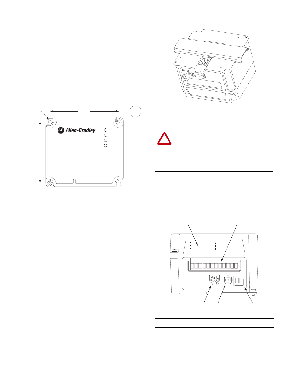
Panel Mounting Using the Dimensional Drawing
Mount the Comms Kit to a panel using two M4 or #8
panhead screws (not included).
shows mounting
dimensions.
Figure 2 Panel Mounting Dimensions
Panel Mounting Procedure Using Comms Kit as a Template
The following procedure enables you to use the assembled
Comms Kit as a template for drilling holes in the panel.
1. Using the assembled Comms Kit as a template, carefully
mark the center of both holes on the panel.
2. Remove the Comms Kit to a clean location.
3. Drill and tap the mounting holes for the recommended
M4 or #8 panhead screws (not included).
4. Place the Comms Kit back on the panel, and check for
proper hole alignment.
5. Attach the Comms Kit to the panel using the mounting
screws.
DIN Rail Mounting
The Comms Kit can be mounted using these DIN rails:
• 35 x 7.5 mm (EN 50 022 - 35 x 7.5)
• 35 x 15 mm (EN 50 022 - 35 x 15)
Before mounting the Comms Kit on a DIN rail, open the
DIN rail latch. Press the DIN rail mounting area of the
Comms Kit against the DIN rail, and manually lock the DIN
rail latch (
Figure 3 DIN Rail Mounting
Electrical Connections
After the communication adapter (and I/O Board option, if
used) is installed and the Comms Kit is mounted, connect all
required cables. See
and its related table showing
the connectors and their connection procedures.
Figure 4 Connecting to the Comms Kit
96,3
(3.79)
85,3
(3.36)
∅ 4
(0.16)
mm
(in.)
PORT
MOD
NET A
NET B
!
ATTENTION: Risk of equipment damage, injury
or death exists. Unpredictable operation may occur
if you fail to verify that parameter settings and
switch settings are compatible with your
application. Verify that settings are compatible
with your application before applying power to the
drive.
Item Description
Connection Procedure
➊
Network
Connector
Connection for the network. Insert the network
cable plug into the mating connector on the
communications adapter.
➋
Optional I/O
Terminal Block
See the I/O Board option (20-XCOMM-IO-
OPT*) Installation Instructions for details.
+ -
➊
➋
➎ ➍
➌
DPI
DC
ADP
DC
+
-