Rockwell Automation 20-XCOMM-IO-OPT1 I/O Board Option 20-XCOMM-IO-OPT1 User Manual
Page 2
www.rockwellautomation.com
Americas: Rockwell Automation, 1201 South Second Street, Milwaukee, WI 53204-2496 USA, Tel: (1) 414.382.2000, Fax: (1) 414.382.4444
Europe/Middle East/Africa: Rockwell Automation, Vorstlaan/Boulevard du Souverain 36, 1170 Brussels, Belgium, Tel: (32) 2 663 0600, Fax: (32) 2 663 0640
Asia Pacific: Rockwell Automation, Level 14, Core F, Cyberport 3, 100 Cyberport Road, Hong Kong, Tel: (852) 2887 4788, Fax: (852) 2508 1846
Power, Control and Information Solutions Headquarters
Publication 20COMM-IN002C-EN-P – May 2007
P/N 328356-P03
Supersedes 20COMM-IN002B-EN-P – July 2006
Copyright © 2007 Rockwell Automation, Inc. All rights reserved. Printed in USA.
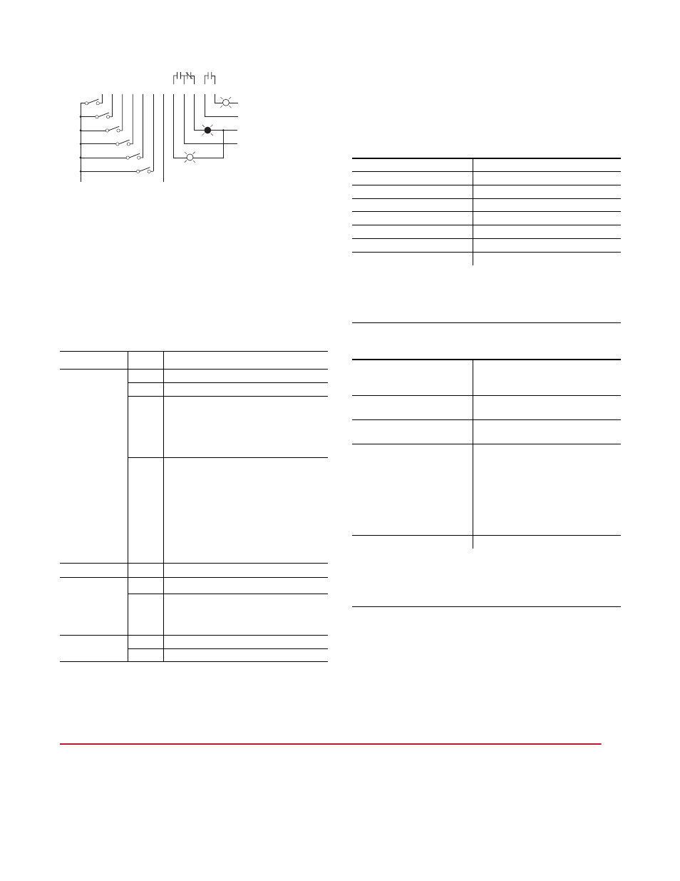
Figure 3 I/O Wiring Example
Configuring the 20-COMM-* Adapter for I/O
When the optional I/O board is installed and the Comms Kit
is mounted and connected, configure the I/O inputs and
outputs. Refer to the communication adapter User Manual
for complete details.
I/O Board LED Indicators
I/O Board Specifications
Inputs
Outputs
LED Name
State
Description
IN1 (Input 1)
Green
Normal operation, Input 1 ON
Off
Normal operation, Input 1 OFF
Solid
Red
Communication with the 20-COMM-*
adapter has not been established.
Possible Reasons: Wrong adapter/series/
firmware (see table above), or bad
connection.
Flashing
Red
Fault - 20-COMM-* adapter has
experienced an Idle or Comm fault, and the
I/O board is taking its configured fault action
for the outputs.
Possible Reasons: Controller in Stop mode
or powered down, DPI connector
disconnected from drive or drive powered
down, or network connector disconnected
from 20-COMM-* adapter.
Orange OPT1 self-diagnostics failure
IN2 (Input 2)
IN3 (Input 3)
IN4 (Input 4)
IN5 (Input 5)
IN6 (Input 6)
Green
Input * ON
(1)
Off
Input * OFF
OUT1 (Output 1)
OUT2 (Output 2)
Green
Output * ON
Off
Output * OFF
1 2 3 4 5 6 7 8 9 10 11 12
(1)
Output commons are isolated.
Power Source (AC or DC)
Power Neutral / Common
(1)
Power Neutral / Common
(1)
Power Source (AC or DC)
0 VDC
(-)
24 VDC
(+)
(1)
These LEDs will indicate input status when the IN1 LED is in normal operation
(Green or Off) and communicating with the Comm adapter. If the IN1 LED
indicates a problem (Solid Red, Flashing Red or Orange), these LEDs will be
turned Off and will not indicate input status.
Number of Inputs
6 (single common)
Input Voltage Type
24 VDC source load
Maximum Input Voltage
27 VDC
Maximum Input Current
8 mA (each input)
Guaranteed ON-State Voltage
10 - 27 VDC (3 mA minimum)
Guaranteed OFF-State Voltage 0 - 5 VDC (2 mA maximum)
Reverse Polarity Protected
-30 VDC
Response Time
25 ms + network update time
The I/O board is NOT designed for fast I/O response times. Do NOT use
with input devices that will transition (OFF
J ON J OFF) faster than the
response time. Potential input devices include auxiliary contact inputs
from relays or overloads, pushbuttons, etc.
Number of Outputs
2 relay outputs (individually isolated)
1 - Form C contacts
1 - Form A (NO) contact
Maximum Output
Contact Voltage
27 VDC / 125 VAC
Maximum Output
Contact Current
2A
Expected Contact Life
1,000,000 cycles resistive at < 0.5A
500,000 cycles inductive at < 0.5A
500,000 cycles resistive at 1A
300,000 cycles inductive at 1A
300,000 cycles resistive at 2A
150,000 cycles inductive at 2A
Response Time
25 ms + network update time
The I/O board is NOT designed for fast I/O response times. Do NOT use
with output devices that need to transition (OFF
J ON J OFF) faster
than the response time. Potential output devices include pilot lights or a
contact closure reset to another hardware device.
U.S. Allen-Bradley Drives Technical Support - Tel: (1) 262.512.8176, Fax: (1) 262.512.2222, Email: [email protected], Online: www.ab.com/support/abdrives