Power wiring, English-6 – Rockwell Automation 22B PowerFlex 40 Quick Start FRN 5.xx - 6.xx User Manual
Page 6
English-6
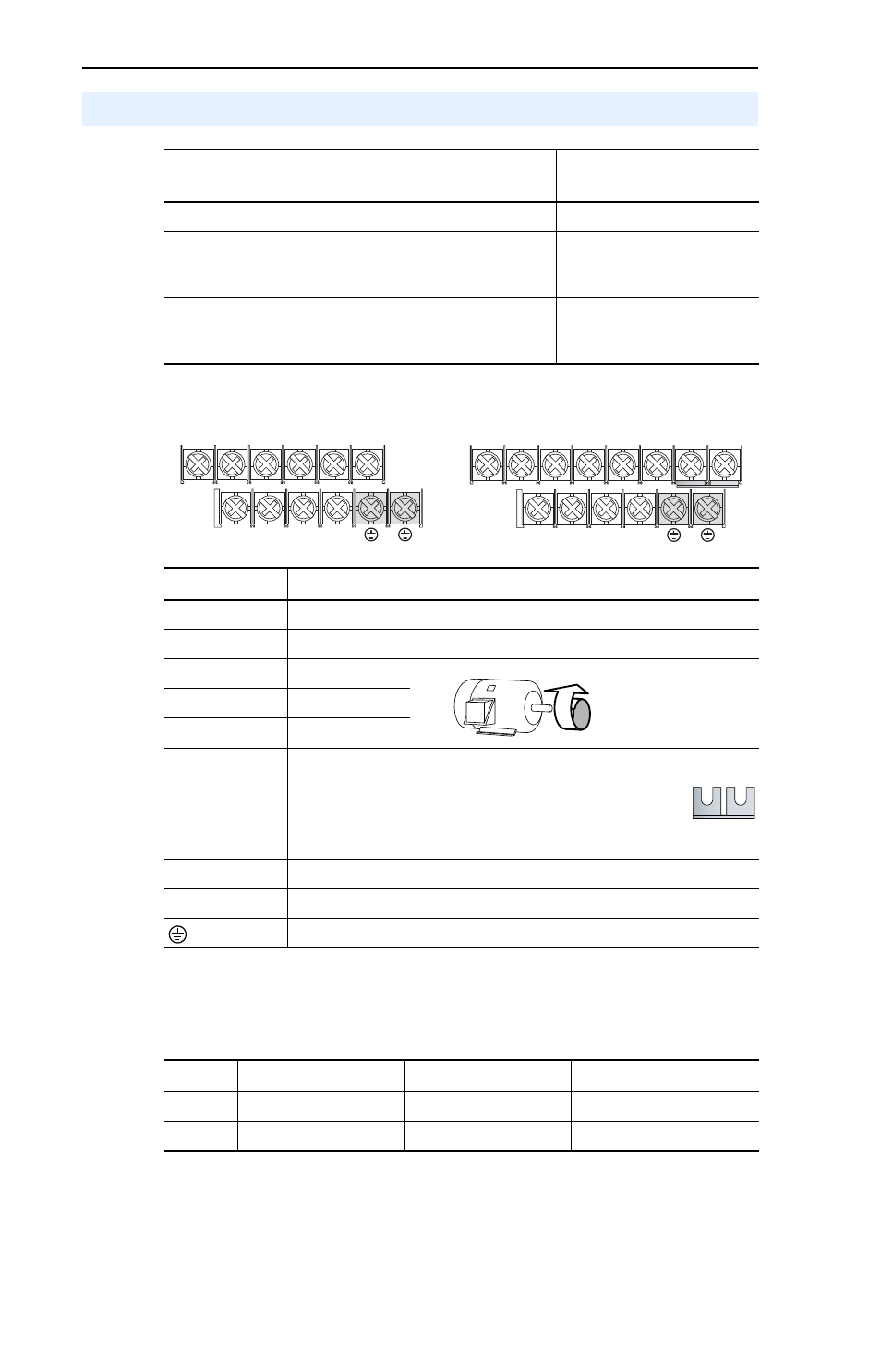
Power Terminal Block
Power Terminal Block Specifications
Power Wiring
Power Wire Rating
Recommended Copper
Wire
Unshielded 600V, 75°C (167°F) THHN/THWN
15 Mils insulated, dry location
Shielded 600V, 75°C or 90°C (167°F or 194°F) RHH/
RHW-2
Anixter OLF-7xxxxx,
Belden 29501-29507 or
equivalent
Shielded Tray rated 600V, 75°C or 90°C (167°F or 194°F)
RHH/RHW-2
Anixter 7V-7xxxx-3G
Shawflex 2ACD/3ACD or
equivalent
Terminal
(1)
Description
R/L1, S/L2
1-Phase Input
R/L1, S/L2, T/L3 3-Phase Input
U/T1
To Motor U/T1
=
Switch any two motor
leads to change
forward direction.
V/T2
To Motor V/T2
W/T3
To Motor W/T3
P2, P1
DC Bus Inductor Connection (C Frame drives only.)
The C Frame drive is shipped with a jumper between
Terminals P2 and P1. Remove this jumper only when a DC
Bus Inductor will be connected. Drive will not power up
without a jumper or inductor connected.
DC+, DC-
DC Bus Connection
BR+, BR-
Dynamic Brake Resistor Connection
Safety Ground - PE
(1)
Important: Terminal screws may become loose during shipment. Ensure that all
terminal screws are tightened to the recommended torque before applying power to
the drive.
Frame
Maximum Wire Size
(2)
Minimum Wire Size
(2)
Torque
B
5.3 mm
2
(10 AWG)
1.3 mm
2
(16 AWG)
1.7-2.2 N-m (16-19 lb.-in.)
C
8.4 mm
2
(8 AWG)
1.3 mm
2
(16 AWG)
2.9-3.7 N-m (26-33 lb.-in.)
(2)
Maximum/minimum sizes that the terminal block will accept - these are not
recommendations.
V/T2
T/L3
S/L2
R/L1
U/T1
W/T3
BR+
BR-
DC- DC+
V/T2
T/L3
S/L2
R/L1
U/T1
W/T3
P2
P1
BR+
BR-
DC- DC+
B Frame
C Frame