Terminal base cable base – Rockwell Automation 42DBS-5100 Background Suppression with Timing PHOTOSWITCH User Manual
Page 3
33
15. Select Light or Dark operate mode with switch.
16. Adjust for the desired delays with the On and Off timing pots.
17. Tighten the lockscrew after adjusting the sensing range. A slight
increase in sensing distance may occur. Typically .25 (.63cm) at
12 (30.5cm), .12 (30.5cm) at a 6 (15.2cm) and .062 (1.57cm)
at 3 (7.62cm), for both background and target. If necessary,
sensing range variation can be compensated for by adjusting to
11.75 (29.8cm) for a 12 (30.5cm) suppression point, 5.875
(14.9cm) for a 6 (15.2cm) suppression point, and 2.95
(7.46cm) for a 3 (7.62cm) suppression point. Repeat steps 5 and
6 to verify the range after the lockscrew is tightened.
APPLICATION PRECAUTIONS
To obtain the high sensitivity and sharp cut-off required in a back-
ground suppression control, two photodetectors are used. One detec-
tor senses objects in close, the other detector will sense further out.
If the further out signal (background) is greater than or equal to
the close in signal, the control remains Off, if the close signal is great-
er than the background signal, the control output will turn On.
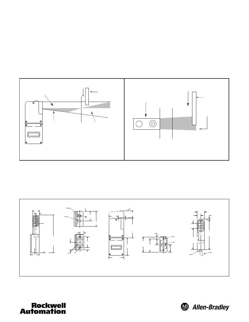
This interdependence of the two photodetectors and overlapping
sensing areas require that the object being sensed passes by the sensor
in certain directions or false operation could occur. Therefore, an ob-
ject always should travel on an x-axis perpendicular with the control.
See figures below.
FIELD OF VIEW
OVERLAP
SUPPRESSION
POINT
FAR SENSING
AREA
OBJECT
TO BE
SUPPRESSED
Direction
of travel
Control
Top View
Suppression
Point
Both
sensing ranges
overlap
OBJECT
TO BE
SUPPRESSED
CLOSE SENSING
AREA
Direction
of travel
WRONG DIRECTION OF TRAVEL
CORRECT DIRECTION OF TRAVEL
INSTALLATION
The control must be securely mounted on a firm, stable surface or
support. A mounting which is subject to excessive vibration or shift-
ing may cause intermittent operation.
OUTLINE DIMENSIONS
QUICK
DISCONNECT
SCREW
1 17/16
(33.3)
1 5/16
(11.9)
15/32
(24.2)
61/64
(139.5)
5 33/64
2 HOLES
10--32 UNF
NPSM
1/2--14
(27.3)
1 5/64
(8.3)
21/64
(38.1)
1 1/2
(13.8)
35/64
(54.7)
2 5/32
(65.8)
2 19/32
(71.0)
2 51/64
(2.7)
7/64
(8.7)MIN.
1 1/32
(36.5)
TO REMOVE SCANNER
LED
INDICATOR
(54.7)
2 5/32
(36.5)
17/16
(19.4)
49/64
3 63/64
(101.2)
61/64
(24.2)
15/32
(11.9)
39/64
(15.4)
2 7/8
(73.0)
1/4-18
NPSM
10’ (3m)
CABLE
7/64
(2.7)
3/4
(19.0
)
21/64
(8.3)
1 1/2
(38.1)
2 5/32
(54.7)
1/4-18
NPSM
10-32 UNC
2 HOLES
1 5/64
(27.3)
TERMINAL BASE
CABLE BASE
(15.4)
39/64