Rockwell Automation 42DBS-5100 Background Suppression with Timing PHOTOSWITCH User Manual
Page 2
22
OPERATING MARGIN
1. The operating margin is parenthesis are for diffuse white surfaces
that fill the control’s field of view.
2. 6.1% and 2.6% designate dark colored surfaces having diffuse re-
flectance of 6.1% and 2.6% respectively compared to diffuse white.
3. The 2.6% surface is Krylon # 1602 Ultra flat black.
TYPICAL SUPPRESSION CURVE
DIST
AN
CE
TO
SE
NSE
D
OB
JEC
T
DISTANCE TO BACKGROUND OBJECT
14
(35.5cm)
12
(30.5cm)
10
(25.4cm)
8
(20.3cm)
6
(15.2cm)
4
(10.1cm)
2
(5.08cm)
0
0
2
(5.08cm)
4
(10.1cm)
6
(15.2cm)
8
(20.3cm)
10
(25.4cm)
12
(30.5cm)
14
(35.5cm)
(O
PERA
TING
M
ARGI
N)
M
-16
(O
PER
AT
IN
G
M
AR
GI
N)
M
-38
WHITE PAPER
6.1%
2.6%
TYPICAL RESPONSE CURVE
OPE
RA
TIN
G
M
AR
GIN
OPERATING DISTANCE
100X
10X
.1”
(.254cm)
1000x
1X
.3”
(.762cm)
.5”
(1.27cm)
.8”
(2.032cm)
2”
(5.08cm)
4”
(10.16cm)
6”
(15.24cm)
8”
(20.3cm)
10”
(25cm)
12”
(30cm)
SUPPRESSION SET FOR 8 (20.3CM)
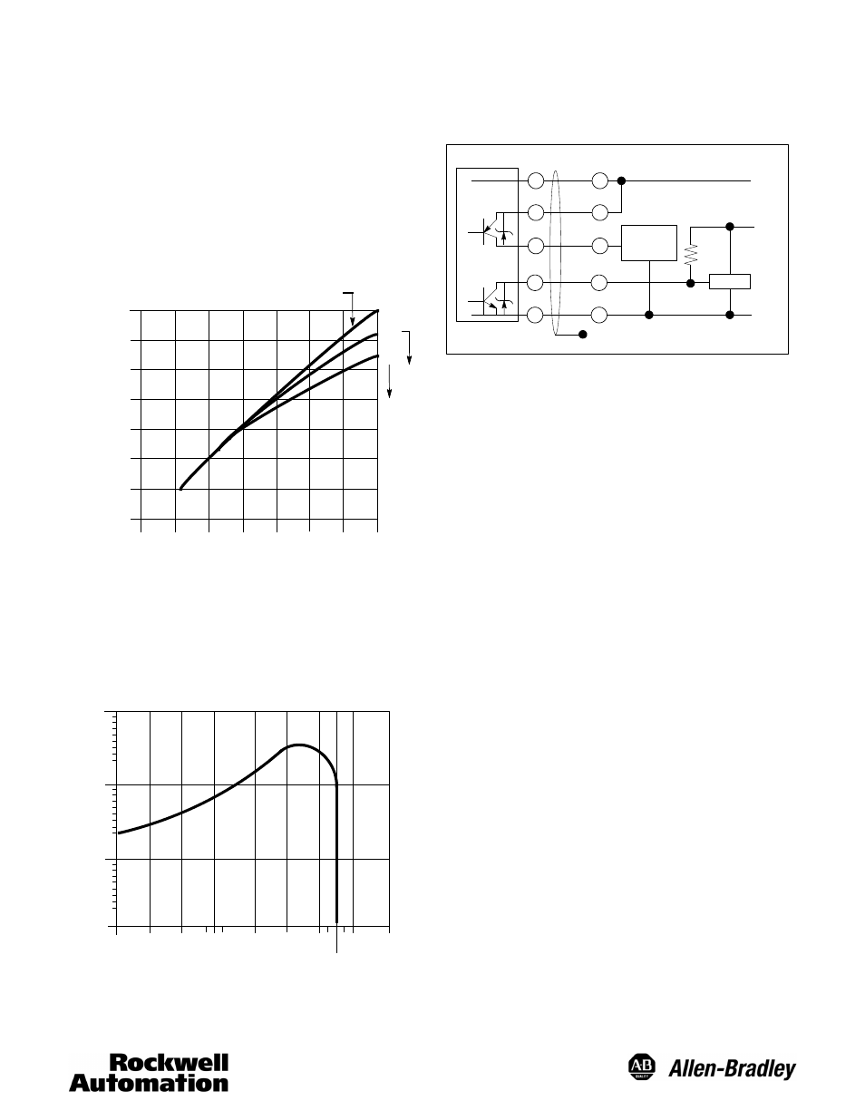
WIRING
All external wiring should conform to the National Electric Code and
applicable local codes. See wiring diagrams for external connections.
TYPICAL WIRING DIAGRAMS
+
(+)
3
2
1
TTL Logic
--
Black
(--)
TERMINAL BASE
Programmable
Controller
DC Interface
10--30VDC
+5VDC
Blue
Grey
Orange
Red
Floating Shield
CABLE BASE
ALIGNMENT
1. Loosen lock to allow sensing range adjustment.
2. Adjust “Coarse” sensing range adjustment to the maximum posi-
tion (full counterclockwise position)
3. Set “Light Energized” (LT)/“Dark Energized” (DK) switch to the
Light Energized position.
4. Select short (0--1.5sec) or Long (0--15sec) “off delay” (one-shot)
switch.
5. Select short (0--1.5sec) or Long (0--15sec) “on delay” (one-shot)
switch.
6. Select “Time delay” (TD) or “One-Shot” (OS) operation switch .
7. Set the on time to minimum, with the on-timing pot. (full counter
clockwise)
8. Set the off-time to maximum, with the off-timing pot, when in
short-off mode (full clockwise) or to at least 2--3 seconds, when
in long-off mode.
9. Turn “coarse” sensing range adjustment to the minimum position
(full clockwise).
10. Position the control in its application and increase the sensing
range until the control senses the background. The Red LED in-
dicator will turn On. The Green LED (2X margin indicator) will
probably turn On.
11. With the “fine” adjustment, decrease the sensing range until the
Green LED turns Off.
12. Place the object to be detected in front of the control at the ex-
pected sensing distance. Both red and green LED’s should turn
On. Remove the target.
13. Time Delay Operation -- If after the off delay has elapsed the
Red LED indicator turns Off, the control has the correct adjust-
ments and settings should be locked with the lock screw. If
the Red LED does not turn Off, slightly reduce the sensing
range with the fine sensing range adjustment and repeat steps
12 and 13.
14. One-Shot Operation -- Replace the target in front of the control
after the one shot time has elapsed. If the Red LED turns On,
the settings are correct and can be locked with the lock screw.
If the Red LED does not turn On, slightly reduce the sensing
range with the fine sensing range adjustment and repeat steps
12 and 14.