2wiring diagrams – Rockwell Automation 42D Series 5000 Blue Line with Analog Output User Manual
Page 2
2
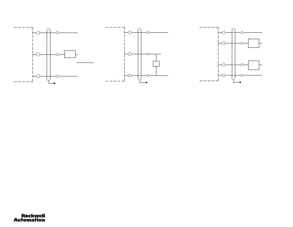
Wiring Diagrams
+
2
--
Floating Shield
Terminal Style
Power Base
Cable Style
Power Base
(+) 22--28V DC
Gray
Black
Analog Current Output Connections
Red
(--)
RMÁX = Supply Voltage -- 10V
20mA
(+) 40V DC Max
Current
Sensor
+
2
--
Analog Voltage Output Connections
(--)
Voltage Sensor
R = 3 k Ohm minimum
Floating Shield
Terminal Style
Power Base
Cable Style
Power Base
(+) 22--28V DC
Gray
Black
Red
Analog Output
+
3
1
--
NPN Set Point Output Connections
(--)
Floating Shield
Terminal Style
Power Base
Cable Style
Power Base
(+) 22--28V DC
Orang
e
Black
Red
Load
100mA
Max.
(+) 10--30V DC
(+) 10--30V DC
Blue
Load
100mA
Max.
Note:
Details of connection of Allen-Bradley Series 5000 photoelectric sensors to Allen-Bradley Programmable Controllers can be found in
Publication 42MR-4.0.
Calibration of the Analog Output is done with a Voltmeter or an Ammeter. When calibrating the Voltage Output, connect
the Voltmeter between Terminal 2 (+) and the negative power supply Terminal 1 (--). Select the Voltmeter Scale for 10V
DC. When calibrating the Current Output, install the Ammeter between Terminal 2 (--) and the positive power supply
Terminal (+), or the positive of a separate power supply when used. Select the Ammeter scale for 20mA (DC).
1. With Selector Switches 1 and 2, select Analog Current or Voltage Output.
2. With Selector Switches 3 and 4, select Positive or Negative Slope operation.
3. Set retroreflective target at 0.61m (2ft). Adjust the Analog Output Calibration pot. for 10V DC or 20mA (2%) when in
Negative Slope operation, or to 1V DC or 1mA (10%) when in Positive Slope operation.
4. Set the retroreflective target at the desired range. 4.57m (15ft) maximum, 1.52m (5ft) minimum. Adjust the Sensing
Range Adjustment pot. for 1V DC or 1mA (10%) when using Negative Slope operation or to 10V DC or 20mA (2%)
when using Positive Slope operation.
5. Bring the retroreflective target back to 0.61m (2ft). Re-adjust the Analog Output Calibration pot. for 10V DC or 20mA
(2%) when using Negative Slope operation or to 1V DC or 1mA when using Positive Slope operation if necessary.
6. Place the retroreflective target at the desired range. Re-adjust the Sensing Range Adjustment pot. for 1V DC or 1mA
(10%) when using Negative Slope operation or to 10V DC or 20mA (2%) when using Positive Slope operation if
necessary.
The Analog Output is now calibrated.
Calibration of Setpoint Outputs
1. Place the retroreflective target at the distance where the Setpoint Output A is to come on.
2. Adjust the Setpoint pot. A to turn on Output A at this point. (Red LED turns on.)
3. Place the retroreflective target at the distance where the Setpoint Output B is to come on.
4. Adjust the Setpoint B to turn on Output B at this point. (Green LED turns on.)
Note:
Be aware that in the retroreflective mode, when setting the range beyond 3.35m (11ft), white paper response may
occur between 2.54cm (1in) and 0.3m (1ft).
This completes the calibration of Setpoint Outputs.