2sensor indicators, Mounting the sensor, Wiring diagrams – Rockwell Automation 42JS VisiSight Photoelectric Sensors User Manual
Page 2
2
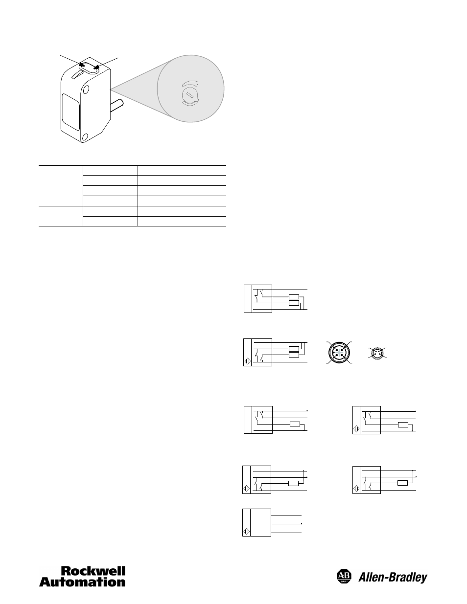
Sensor Indicators
Green LED
Yellow Output
LED
Sensitivity
Adjustment
Knob
min
max
LED Status
Green
OFF
Power is Off
ON
Power is On
Flashing (6 Hz)
Unstable ( 0.5 < Margin < 2)
Flashing (1.5 Hz)
Output short-circuit protection active
Yellow
OFF
Output de-energized
ON
Output energized
Black wire or pin 4 of connector.
Sensor Alignment
1. Ensure that the sensitivity knob is set at its maximum
(factory default) setting.
2. Pan the sensor left, right, up and down to center the beam
on the sensed object (for diffuse), reflector (for
retroreflective) or transmitter (for transmitted beam). Fix the
sensor position when the green LED is ON (not flashing)
and the yellow output LED is ON (light sensed and L.O.
output energized). This set up assures a good margin and
that signal received is greater than twice the signal
required to energize the L.O output.
3.
a. For diffuse applications, remove the object being sensed
and observe the green LED. If the green LED is flashing
(at 6 Hz), it indicates that sensor is receiving more than
half the signal required to energize the L.O. output when
there should be minimal or no received signal. It
indicates that the sensor is getting close to detection of
background. Stability may be optimized by reducing the
reflectivity of the background or reducing the sensitivity.
Reducing the sensitivity shortens the sensing range. If
sensitivity is reduced, check that both the green and
yellow LEDs are on when the object is detected (step 2
above). In applications where full range is needed, i.e.,
sensitivity cannot be reduced, the green LED may be
left flashing.
b. For retroreflective and transmitted beam applications,
place the object to be sensed in the beam path and
observe the green LED. If the green LED is flashing (at
6 Hz), it indicates that sensor is receiving more than half
the signal required to energize the L.O. output when
there should be minimal or no received signal. It
indicates that the object being detected is letting some
light go through (semi-transparent or too small in size).
Adjust sensitivity and repeat step 2.
Crosstalk Avoidance
For applications of transmitted beam sensors requiring
adjacent pairs to be mounted in close proximity, use red LED
and infrared LED pairs as adjacent pairs.
The following spacing (center to center) between the adjacent
pairs should be maintained to avoid crosstalk:
1. Red LED pair adjacent to infrared LED pair:
a. 60 mm (2.4 in.) for sensing range up to 1.6 m (4.8 ft)
b. 20 mm (0.8 in.) for sensing range greater than 1.6 m
(4.8 ft)
2. Two adjacent pairs of red LED models or two adjacent
pairs of infrared LED: 360 mm (14 in.)
Four pairs can be mounted within the same spacing by
alternating the transmitter/receiver position.
Mounting the Sensor
Securely mount the sensor on a firm, stable surface or
support. A mounting which is subject to excessive vibration or
shifting may cause intermittent operation. Adaptors and
mounting brackets are available for a flexible installation. See
Accessories section for more details.
Wiring Diagrams
Cable connection is shown in the following diagrams. Pin
numbers correspond to an M12 or M8 male connector on the
sensor.
PNP Models with Complementary Outputs
Brown (1)
White (2)
Black (4)
Blue (3)
Load
Load
+
–
LO
DO
NPN Models with Complementary Outputs
4
3
1
2
3
2
1
4
Brown (1)
White (2)
DO
Black (4)
Blue (3)
Load
Load
+
–
LO
M12 Male
M8 Male
PNP Diagnostic Models
Light Operate
Dark Operate
Brown (1)
White (2)
Black (4)
Blue (3)
Load
+
–
LO
Diag
Brown (1)
White (2)
Black (4)
Blue (3)
Load
+
–
DO
Diag
NPN Diagnostic Models
Light Operate
Dark Operate
Transmitted Beam Emitter
Brown (1)
White (2)
Diag
Black (4)
Blue (3)
Load
+
–
LO
Brown (1)
White (2)
Diag
Black (4)
Blue (3)
Load
+
–
DO
Brown (1)
Black (4)
Blue (3)
+
–
Diagnostic output is energized if the sensor operation is unstable.
For normal operation, black wire (pin 4) needs no connection. To disable light source, connect
black wire (pin 4) to +V.