Display group parameters, Smart start-up with basic program group parameters, English-9 – Rockwell Automation 22A PowerFlex 4 Quick Start FRN 6.xx User Manual
Page 9
English-9
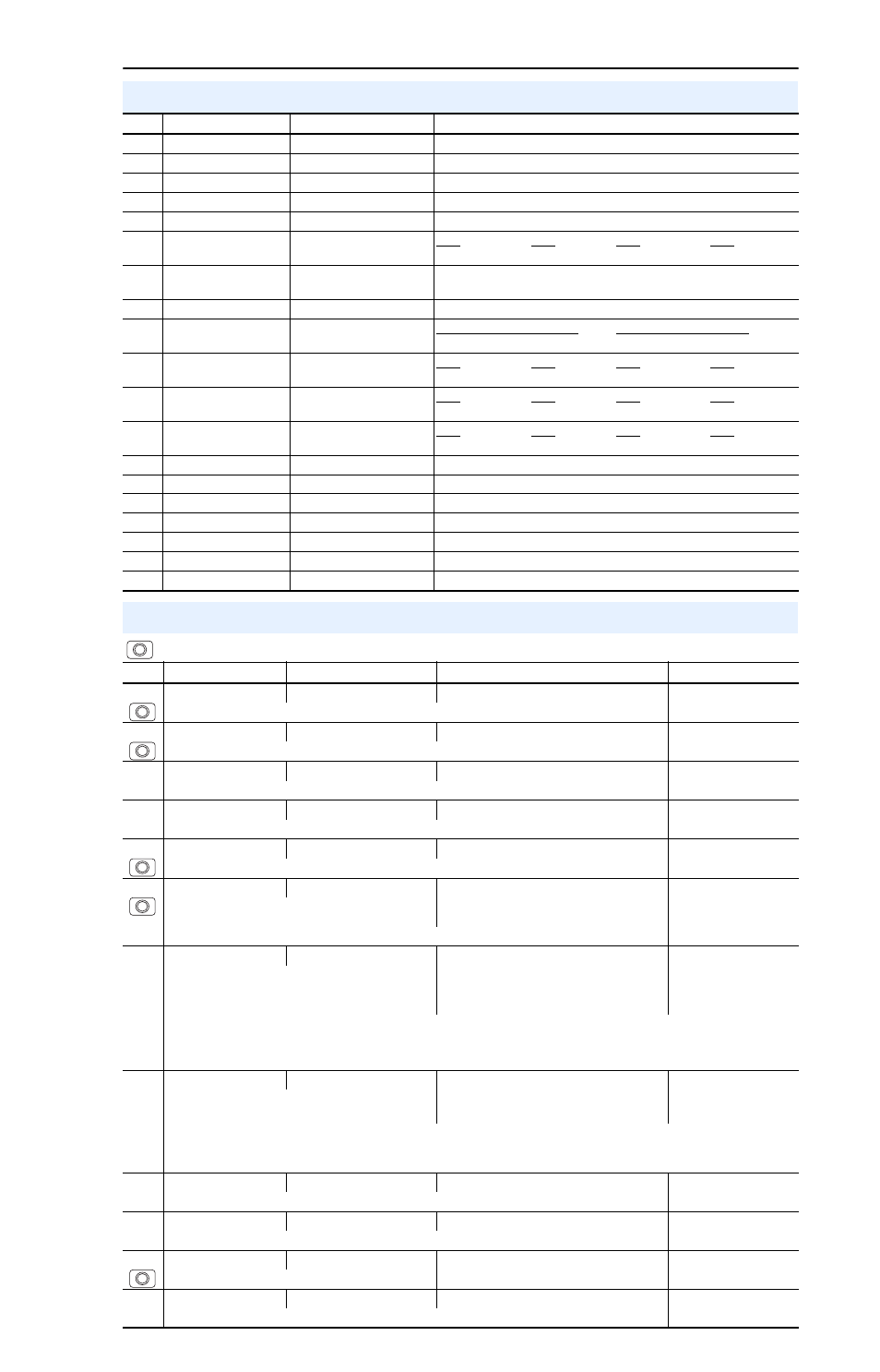
Display Group Parameters
No.
Parameter
Min/Max
Display/Options
d001 [Output Freq]
0.0/[Maximum Freq]
0.1 Hz
d002 [Commanded Freq]
0.0/[Maximum Freq]
0.1 Hz
d003 [Output Current]
0.00/(Drive Amps
×
2)
0.01 Amps
d004 [Output Voltage]
0/Drive Rated Volts
1 VAC
d005 [DC Bus Voltage]
Based on Drive Rating
1 VDC
d006 [Drive Status]
0/1 (1 = Condition True)
Bit 3
Bit 2
Bit 1
Bit 0
Decelerating
Accelerating
Forward
Running
d007-
d009
[Fault x Code]
F2/F122
F1
d010 [Process Display]
0.00/9999
0.01 – 1
d012 [Control Source]
0/9
Digit 1 = Speed Command
Digit 0 = Start Command
(See P038; 9 = “Jog Freq”)
(See P036; 9 = “Jog”)
d013 [Contrl In Status]
0/1 (1 = Input Present)
Bit 3
Bit 2
Bit 1
Bit 0
Reserved
Stop Input
Dir/Run REV
Start/Run FWD
d014 [Dig In Status]
0/1 (1 = Input Present)
Bit 3
Bit 2
Bit 1
Bit 0
Reserved
Reserved
Digital In2 Sel
Digital In1 Sel
d015 [Comm Status]
0/1 (1 = Condition True)
Bit 3
Bit 2
Bit 1
Bit 0
Fault Occurred
RS485 Option Transmitting
Receiving
d016 [Control SW Ver]
1.00/99.99
0.01
d017 [Drive Type]
1001/9999
1
d018 [Elapsed Run Time]
0/9999 Hrs
1 = 10 Hrs
d019 [Testpoint Data]
0/FFFF
1 Hex
d020 [Analog In 0-10V]
0.0/100.0%
0.1%
d021 [Analog In 4-20mA]
0.0/100.0%
0.1%
d024 [Drive Temp]
0/120 degC
1 degC
Smart Start-Up with Basic Program Group Parameters
= Stop drive before changing this parameter.
No.
Parameter
Min/Max
Display/Options
Default
P031 [Motor NP Volts]
20/Drive Rated Volts
1 VAC
Based on Drive Rating
Set to the motor nameplate rated volts.
P032 [Motor NP Hertz]
10/240 Hz
1 Hz
60 Hz
Set to the motor nameplate rated frequency.
P033 [Motor OL Current]
0.0/(Drive Rated Amps
×
2) 0.1 Amps
Based on Drive Rating
Set to the maximum allowable motor current.
P034 [Minimum Freq]
0.0/240.0 Hz
0.1 Hz
0.0 Hz
Sets the lowest frequency the drive will output continuously.
P035 [Maximum Freq]
0/240 Hz
1 Hz
60 Hz
Sets the highest frequency the drive will output.
P036 [Start Source]
0/5
0 = “Keypad”
(1)
1 = “3-Wire”
2 = “2-Wire”
3 = “2-W Lvl Sens”
4 = “2-W Hi Speed”
5 = “Comm Port”
0
Sets the control scheme used to start the drive.
(1)
When active, the Reverse key is also active unless disabled by A095 [Reverse Disable].
P037 [Stop Mode]
0/7
0 = “Ramp, CF”
(1)
1 = “Coast, CF”
(1)
2 = “DC Brake, CF”
(1)
3 = “DCBrkAuto,CF”
(1)
4 = “Ramp”
5 = “Coast”
6 = “DC Brake”
7 = “DC BrakeAuto”
0
Active stop mode for all stop sources [e.g. keypad,
run forward (I/O Terminal 02), run reverse (I/O
Terminal 03), RS485 port] except as noted below.
Important: I/O Terminal 01 is always a coast to stop input except when P036 [Start Source] is set for “3-Wire” control.
When in three wire control, I/O Terminal 01 is controlled by P037 [Stop Mode].
(1)
Stop input also clears active fault.
P038 [Speed Reference]
0/5
0 = “Drive Pot”
1 = “InternalFreq”
2 = “0-10V Input”
3 = “4-20mA Input”
4 = “Preset Freq”
5 = “Comm Port”
0
Sets the source of the speed reference to the
drive.
Important: When A051 or A052 [Digital Inx Sel] is set to option 2, 4, 5, 6, 13 or 14, and the digital input is active, A051
or A052 will override the speed reference commanded by this parameter. Refer to Chapter 1 of the PowerFlex 4 User
Manual for details.
P039 [Accel Time 1]
0.0/600.0 Secs
0.1 Secs
10.0 Secs
Sets the rate of accel for all speed increases.
P040 [Decel Time 1]
0.1/600.0 Secs
0.1 Secs
10.0 Secs
Sets the rate of decel for all speed decreases.
P041 [Reset To Defalts]
0/1
0 = “Idle State”
1 = “Reset Defaults”
0
Resets all parameter values to factory defaults.
P043 [Motor OL Ret]
0/1
0 = “Disabled”
1 = “Enabled”
0
Enables/disables the Motor Overload Retention function.
See the PowerFlex 4 User Manual for more information on parameters.