Power wiring, I/o wiring recommendations, I/o terminal block specifications – Rockwell Automation 22A PowerFlex 4 Quick Start FRN 6.xx User Manual
Page 4: English-4
English-4
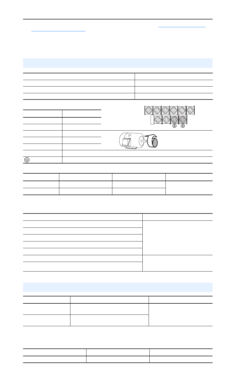
Power Terminal Block (A Frame Shown)
Power Terminal Block Specifications
Input Power Conditions
I/O Terminal Block Specifications
(2)
The AIC ratings of the Bulletin 140M Motor Protector Circuit Breakers may vary. See
(3)
Manual Self-Protected (Type E) Combination Motor Controller, UL listed for 208 Wye or Delta, 240 Wye or Delta, 480Y/
277 or 600Y/347. Not UL listed for use on 480V or 600V Delta/Delta, corner ground, or high-resistance ground systems.
(4)
When using a Manual Self-Protected (Type E) Combination Motor Controller, the drive must be installed in a ventilated or
non-ventilated enclosure with the minimum volume specified in this column. Application specific thermal considerations
may require a larger enclosure.
Power Wiring
Power Wire Rating
Recommended Copper Wire
Unshielded 600V, 75°C (167°F) THHN/THWN
15 Mils insulated, dry location
Shielded 600V, 75°C or 90°C (167°F or 194°F) RHH/RHW-2
Belden 29501-29507 or equivalent
Shielded Tray rated 600V, 75°C or 90°C (167°F or 194°F) RHH/RHW-2
Shawflex 2ACD/3ACD or equivalent
V/T2
T/L3
S/L2
R/L1
U/T1
W/T3
BR+
BR-
Terminal
Description
R/L1, S/L2
1-Phase Input
R/L1, S/L2, T/L3
3-Phase Input
U/T1
To Motor U/T1
=
Switch any two motor leads to
change forward direction.
V/T2
To Motor V/T2
W/T3
To Motor W/T3
BR+, BR-
Dynamic Brake Resistor Connection [0.75 kW (1 HP) ratings and higher]
Safety Ground - PE
Frame
Maximum Wire Size
(1)
Minimum Wire Size
(1)
Torque
A
3.3 mm
2
(12 AWG)
0.8 mm
2
(18 AWG)
1.7-2.2 N-m (16-19 lb.-in.)
B
5.3 mm
2
(10 AWG)
1.3 mm
2
(16 AWG)
(1)
Maximum/minimum sizes that the terminal block will accept - these are not recommendations.
Input Power Condition
Corrective Action
Low Line Impedance (less than 1% line reactance)
•
Install Line Reactor
(2)
•
or Isolation Transformer
Greater than 120 kVA supply transformer
Line has power factor correction capacitors
Line has frequent power interruptions
Line has intermittent noise spikes in excess of 6000V (lightning)
Phase to ground voltage exceeds 125% of normal line to line voltage
•
Remove MOV jumper to ground.
•
or Install Isolation Transformer with
grounded secondary if necessary.
Ungrounded Distribution System
(2)
Refer to Appendix B of the PowerFlex 4 User Manual for accessory ordering information.
I/O Wiring Recommendations
(3)
Wire Type(s)
Description
Minimum Insulation Rating
Belden 8760/9460
(or equiv.)
0.8 mm
2
(18AWG), twisted pair, 100% shield with
drain.
300V
60 degrees C
(140 degrees F)
Belden 8770
(or equiv.)
0.8 mm
2
(18AWG), 3 conductor, shielded for
remote pot only.
(3)
If the wires are short and contained within a cabinet which has no sensitive circuits, the use of shielded wire may not be
necessary, but is always recommended.
Maximum Wire Size
(4)
Minimum Wire Size
(4)
Torque
1.3 mm
2
(16 AWG)
0.13 mm
2
(26 AWG)
0.5-0.8 N-m (4.4-7 lb.-in.)
(4)
Maximum / minimum that the terminal block will accept - these are not recommendations.