Step 5: install the new pulse transformer board – Rockwell Automation 20P PowerFlex DC Drive - Frame C Pulse Transformer Circuit Board User Manual
Page 14
14
Rockwell Automation Publication 20P-IN010C-EN-P - February 2012
PowerFlex DC Drive Frame C Pulse Transformer Circuit Board
Step 5: Install the New
Pulse Transformer
Board
Install the new Pulse Transformer board in reverse order of removal as detailed in
Step 3:
Remove the Existing Pulse Transformer Board on page 4
.
1. Inspect the existing connection cables for burn marks, cracks or loose
connectors. If necessary, replace the cables connected to connector X3, X4,
X5, XCD, XR, XSW, XTA and XUVW on the Pulse Transformer board
with the new cables provided.
2. Inspect the existing gate lead cables for burn marks, cracks or loose
connectors. If necessary, replace the gate lead cables with the new cables
provided.
Step 6: Replace the
Protective Covers
and Documenting
the Change
1. Replace the protective covers in the reverse order of removal as described
in Step 2:
Remove the Protective Covers on page 3
.
2. Install DPI cable (if present).
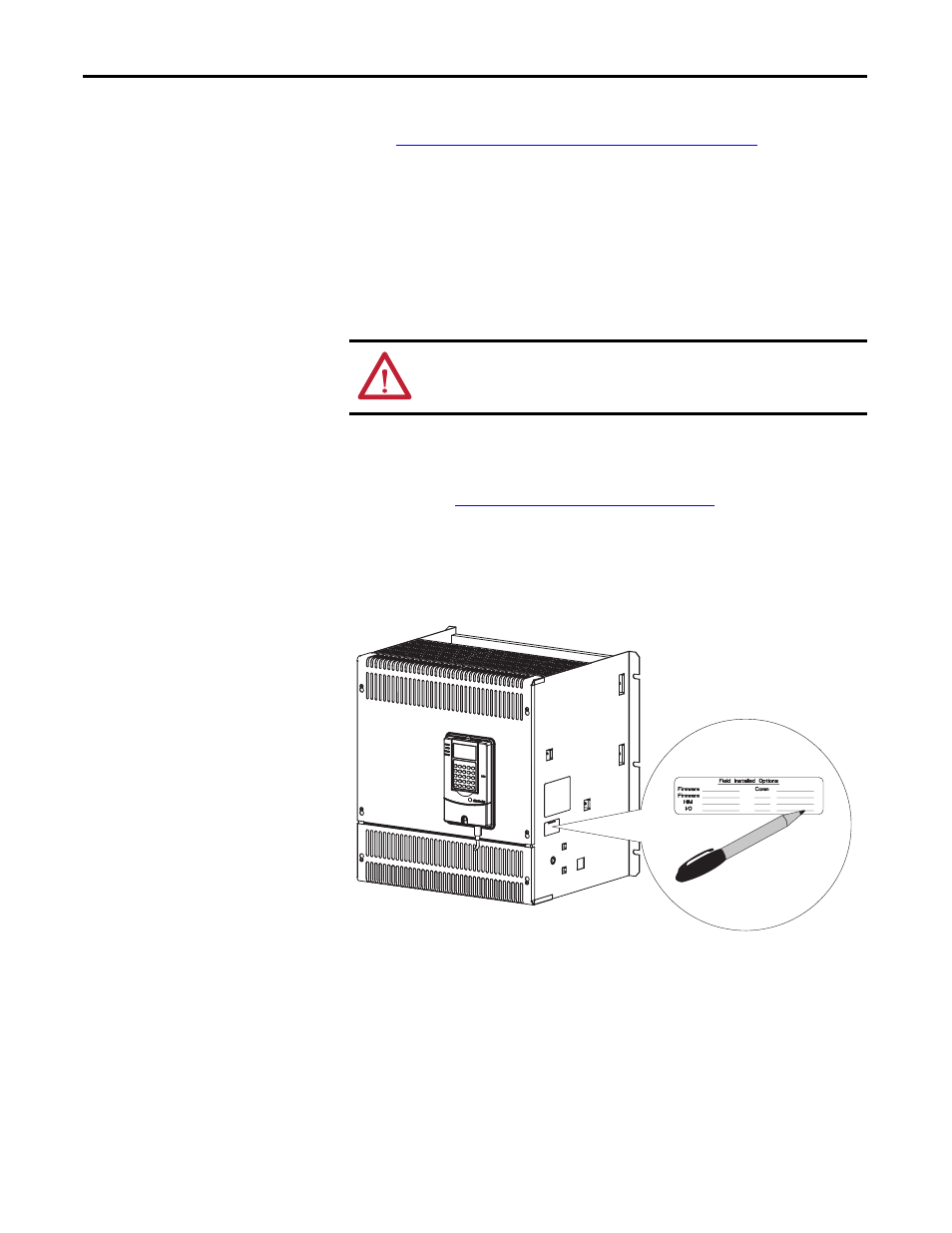
3. Record the installation of the new Pulse Transformer board and date of
installation on the Field Installed Option label on the side of the drive (as
shown below).
ATTENTION: Each gate lead cable must be connected to the exact connector
from which it was removed on the Pulse Transformer circuit board or damage to
the drive may occur.