Setting the discrete output: q1 – Rockwell Automation 45LMS Laser Measurement Sensor User Manual
Page 3
3
After the LED
s
fl
as
h
s
im
u
lt
a
neo
us
ly, they fl
as
h
a
ltern
a
tely to
indic
a
te whether the Te
a
ch w
as
su
cce
ss
f
u
l:
Su
cce
ss
f
u
l:
s
lower
a
ltern
a
ting fl
as
hing (2.5 Hz)
Un
su
cce
ss
f
u
l: f
as
ter
a
ltern
a
ting fl
as
hing (
8
Hz).
¹
Set-points can be independently taught. For example, set-point
Q1-B can be set/re-taught without changing set-point Q1-A.
By pressing the SET button for >5 s when Q1-A, Q1-B or Q2-A is
selected with the Rotary Switch, the taught value for that set-point
is deleted, leaving the sensor with no value for the set-point that
was selected. When you delete Q2-A, the analog output changes
to Zero Point mode (see “Zero Point (Positive Slope)” on page 4
for details). Note that the value for Q2-B cannot be deleted, it can
only be overwritten.
When switching between discrete sensing modes, it is necessary
to delete or teach the set-points for both Q1-A and Q1-B.
Setting the discrete output: Q1
The discrete NPN/PNP output can be set as a switchpoint or
switching window as described below.
These instructions were made with the assumption that the
sensor is being used for Light Operate and that a PNP output is
desired. If the required output is NPN, then refer to the rotary
positions listed in the parentheses () throughout the Discrete
Output instructions.
Switch-point and closer
This is the most commonly used mode for object detection with
background suppression. If using the sensor for this type of
application set the Teach-point at the farthest distance from the
sensor that the target will pass.
When using this mode, the sensor output will turn on if it detects
an object between 200 mm (8 in.) from the sensor face and up to
the Teach-point. For example, if the Teach-point is set at 2 m (6.6
ft), the output would turn on if the sensor detects an object
anywhere between 200 mm and 2 m.
1. Place a target at the desired Teach-point, move the Rotary
Switch to position Q1-B (Q1-A for NPN).
2. Press and hold the SET button until the Green and Yellow
LEDs flash simultaneously
1
.
3. If the Teach is successful, move the Rotary Switch to RUN.
The remainder of these instructions refer to the 24V
state as ON and the 0V state as OFF (PNP). If wired
as NPN, the logic is inverted.
Please note that when you use the sensor for an
NPN output, the Yellow LED will behave opposite to
the sensor output.
For example, when the NPN output is ON, the
Yellow LED will be OFF.
IMPORTANT
IMPORTANT
24 V
0 V
0.2 m
Q1B
MAX
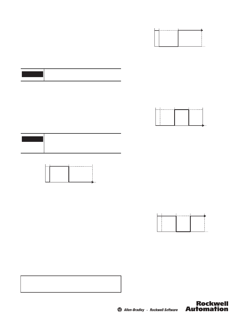
Switch-point and farther
In this mode, the sensor output will turn on if it detects an object
at the Teach-point or at any distance farther than the Teach-point
up to the maximum range of the sensor. For example, if the
Teach-point is at 2 m, the output will turn on if the sensor detects
an object anywhere from 2 m to the maximum range.
1. Place a target at the desired Teach-point, move the Rotary
Switch to position Q1-A (Q1-B for NPN).
2. Press and hold the SET button until the Green and Yellow
LEDs flash simultaneously
1
.
3. If the Teach is successful, move the Rotary Switch to RUN.
Switching window
When setting the sensor this way, the output will turn on when it
detects an object within a window created between two Teach-
points. For example, if the Teach-point for Q1-A is set at 2 m, and
the Teach-point for Q1-B is set at 3 m, the sensor will turn the
output on if it detects an object between 2 and 3 m.
1. Place a target at the closer (relative to the sensor) desired
Teach-point, move the Rotary Switch to position Q1-A
(Q1-B for NPN).
2. Press and hold the SET button until the Green and Yellow
LEDs flash simultaneously
1
.
3. Place a target at the farther (relative to the sensor) desired
Teach-point, move the Rotary Switch to position Q1-B
(Q1-A for NPN).
4. Press and hold the SET button until the Green and Yellow
LEDs flash simultaneously
1
.
5. If the Teach is successful, move the Rotary Switch to RUN
Switching window (inverted)
When setting the sensor this way, the output will turn on when
there is no object detected within the defined window created
between 2 Teach-points. For example, if the Teach-point for Q1-B
is set at 2 m, and the Teach-point for Q1-A is set at 3 m, the
sensor will remain on as long as there is no object detected
between 2 and 3 m.
1. Place a target at the closer (relative to the sensor) desired
Teach-point, and move the Rotary Switch to position Q1-B
(Q1-A for NPN).
2. Press and hold the SET button until the Green and Yellow
LEDs flash simultaneously
1
.
24 V
0 V
0.2 m
Q1A
MAX
24 V
0 V
0.2 m
Q1B
MAX
Q1A
24 V
0 V
0.2 m
Q1A
MAX
Q1B