Rockwell Automation 42DRC-5400 Retroreflective/Diffuse PHOTOSWITCH User Manual
Installation instructions photoswitch
1
INSTALLATION INSTRUCTIONS PHOTOSWITCH
RETROREFLECTIVE/DIFFUSE CONTROL, BULLETIN 42DRC-5400
IMPORTANT: SAVE THESE INSTRUCTIONS FOR FUTURE USE. FOR ADDITIONAL INFORMATION REFER TO PUBLICATION PG-9000
BULLETIN NUMBER
VOLTAGE
SUPPLY
SUPPLY
CURRENT
OUTPUT CHARACTERISTIC
RESPONSE
TIME
OPERATING DISTANCE
PHOTOHEAD
POWERBASE
TYPE
RATING
LEAKAGE
(OFF STATE)
RETRO TAPE
#7590
15 X 15 (.38 X .38)
LINEAR
RESPONSE
DIFFUSE
WHITE
PAPER
LINEAR
RESPONSE
42DRC- 5400
—
—
—
Analog Voltage 1--10VDC
—
100ms
2--15
(.61m--4.57m)
5--13
(1.22m--
4.27m)
6--5
(.15m--
1.5m)
2--4
(.61m--
1.2m)
Analog Current
1--20mA
—
Two
Adjustable Set
Points NPN
100mA
10A
42DTB-5000
TERMINAL
22--28
VDC
70mA
42DCB-5000
CABLE
SPECIFICATIONS:
Voltage Supply to Analog Output (Terminal 2):
Current Output
40VDC Max.
. . . . . . . . . . . . . . . . . . . . . . . . . . .
Voltage Output
0 V
. . . . . . . . . . . . . . . . . . . . . . . . . . . . . . . . . . . .
Output Indicators
Setpoint A
Red LED
. . . . . . . . . . . . . . . . . . . . . . . . . . . . . . . . . . .
Setpoint B
Green LED
. . . . . . . . . . . . . . . . . . . . . . . . . . . . . . . . .
Setpoint Adjustment
Yes
. . . . . . . . . . . . . . . . . . . . . . . . . . . . . . . .
Setpoint Output Differential
15%
. . . . . . . . . . . . . . . . . . . . . . . . .
Slope
Selectable Positive or Negative
. . . . . . . . . . . . . . . . . . . . . . .
Reverse Polarity Protection
Yes
. . . . . . . . . . . . . . . . . . . . . . . . . . .
Transient Noise Protection
Yes
. . . . . . . . . . . . . . . . . . . . . . . . . . .
Short Circuit Protection
Analog Output only
. . . . . . . . . . . . . . . .
Analog Output Calibration
Yes
. . . . . . . . . . . . . . . . . . . . . . . . . . .
Sensing Range Adjustment
Yes
. . . . . . . . . . . . . . . . . . . . . . . . . . .
Temperature Compensation
Yes
. . . . . . . . . . . . . . . . . . . . . . . . . .
Field of View
3
. . . . . . . . . . . . . . . . . . . . . . . . . . . . . . . . . . . . . . . .
Transmitting LED
Infrared, 880nm
. . . . . . . . . . . . . . . . . . . . . . . .
Operating Environment: NEMA 3, 4, 12, 13, and IP66 (IEC529)
Approvals
UL Listed and CSA Certified
. . . . . . . . . . . . . . . . . . . .
Housing Material
High impact chemically resistant Valox
. . . . .
Ambient Temperature Range
--40
o
F to 150
o
F (--40
o
C to 65
o
C)
. .
Relative Humidity
90%
. . . . . . . . . . . . . . . . . . . . . . . . . . . . . . . . .
Terminations
Cable Base:
Supplied with 10 (3m) of 5-conductor,
. . . . . . . . . .
flexible, vinyl-covered cable
Terminal Base:
Supplied with #6/32 nickel plated brass
. . . . . . .
pressure type terminals
ACCESSORIES
1. Reflector
PART NUMBER
SIZE
92-39
3 (78mm)
92-47
1.25 (32mm)
92-46
.625 (16mm)
2. Optional Mounting Assemblies
PART NUMBER
DESCRIPTION
60-1577
Armored Cable Adapter
60-1785
Universal Mounting Assembly
60-1748
Heavy Duty Mounting Assembly
60-2014
Flexi-mount Mounting Assembly
60-2083
Photoguard Heavy Duty Protection
60-2213
Conduit Mounting Adapter
60-2230
Limit Switch Type Mounting Assembly
61--5540
NEMA 7 & 9 Enclosure
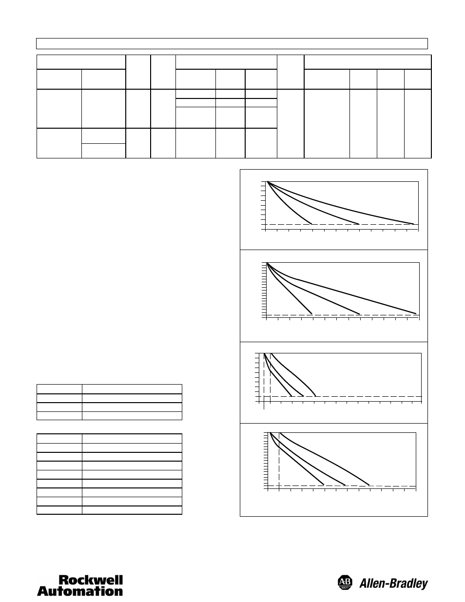
OPERATING DISTANCE SELECTION
The maximum operating distance is based on installing the con-
trol in a relatively clean environment. Normal industrial environment
actually ranges from moderately Dusty to extremely Dirty.
Greater operating margin (excess gain) may be required, which
can be obtained by reducing the operating distance of the control.
TYPICAL RESPONSE CURVES
OPERATING DISTANCE
DC
VO
LT
AG
E
2’
(.6m)
3’
(.9m)
4’
(1.2m)
5’
(1.5m)
6’
(1.8m)
7’
(2.1m)
8’
(2.4m)
9’
(2.7m)
10’
(3m)
11’
(3.3m)
12’
(3.6m)
13’
(3.9m)
14’
(4.2m)
15’
(4.5m)
1
2
3
4
5
6
7
8
9
10
RETROREFLECTIVE VOLTAGE OUTPUT
0
CALIBRATED BETWEEN:
A: 2’--15’ (.6m--4.5m)
B: 2’--10’ (.6m--3m)
C: 2’--6’ (.6m--1.8m)
A
B
C
OPERATING DISTANCE
DC
CU
RR
ENT
(m
A)
2’
(.6m)
3’
(.9m)
4’
(1.2m)
5’
(1.5m)
6’
(1.8m)
7’
(2.1m)
8’
(2.4m)
9’
(2.7m)
10’
(3m)
11’
(3.3m)
12’
(3.6m)
13’
(3.9m)
14’
(4.2m)
15’
(4.5m)
2
4
6
8
10
12
14
16
18
20
RETROREFLECTIVE CURRENT OUTPUT
0
1
A
B
C
CALIBRATED BETWEEN:
A: 2’--15’ (.6m--4.5m)
B: 2’--10’ (.6m--3m)
C: 2’--6’ (.6m--1.8m)
OPERATING DISTANCE
DC
VO
LT
AG
E
2’
(.6m)
3’
(.9m)
4’
(1.2m)
5’
(1.5m)
6’
(1.8m)
7’
(2.1m)
8’
(2.4m)
9’
(2.7m)
10’
(3m)
11’
(3.3m)
12’
(3.6m)
13’
(3.9m)
14’
(4.2m)
15’
(4.5m)
1
2
3
4
5
6
7
8
9
10
DIFFUSE VOLTAGE OUTPUT
0
CALIBRATED BETWEEN:
A: 1’--5’ (.3m--1.5m)
B: 6”--4’ (15cm--1.2m)
C: 6”--3’ (15cm--.9m)
1’
(.3m)
0
6”
(15cm)
A
B
C
OPERATING DISTANCE
DC
CU
RR
ENT
(m
A)
0.5’
(.15m)
1.0’
(.3m)
1.5’
(.45m)
2.0’
(.6m)
2.5’
(.75m)
3.0’
(.9m)
3.5’
(1m)
4’
(1.2m)
4.5’
(1.3m)
5’
(1.5m)
5.5’
(1.6m)
6.0’
(1.8m)
6.5’
(1.9m)
7.0’
(2.1m)
2
4
6
8
10
12
14
16
18
20
DIFFUSE CURRENT OUTPUT
0
1
CALIBRATED BETWEEN:
A: 1’--2” (.3m--5cm)
B: 6”--4’ (15cm--1.2m)
C: 6”--3’ (15cm--.9m)
C
B
A
CALIBRATION PROCEDURES
Before starting the calibration procedures for Analog Output or
Setpoint Output, be sure the control is at the same temperature as it’s
environment; it adjusts after approximately 15 minutes. Setpoint Cal-
ibration is best performed after calibration of the Analog Output has
been completed.