Typical response curves, Sensor dimensions—mm (inches) wiring diagram – Rockwell Automation 42EF RightSight DeviceNet Photoelectric Sensors User Manual
Page 2
2
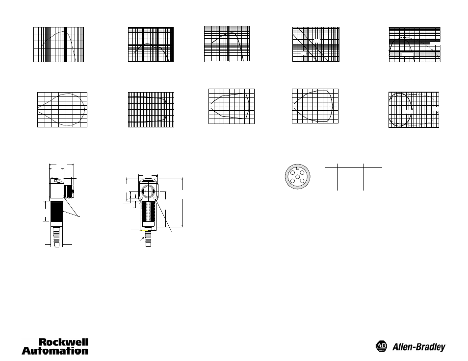
Typical Response Curves
Polarized Retroreflective
Diffuse
1
10
100
O
per
at
in
g
M
ar
gi
n
0.1
(0.04)
1
(0.4)
10
(3.9)
100
(39)
Distance to White Target—cm (in)
Background Suppression
O
per
at
in
g
M
ar
gi
n
0.01
(0.03)
0.1
(0.328)
1
(3.28)
10
(32.8)
Distance to 76mm Reflector, 92- 39—m (ft)
6
5
4
3
2
1
1
10
100
1000
0
20
(0.7)
40
(1.5)
60
(2.3)
80
(3.1)
100
(3.9)
Distance to White Target—mm (in)
O
per
at
in
g
M
ar
gi
n
100mm
50mm
Sharp Cutoff Diffuse
1
10
100
2.54
(0.1)
25.4
(1.0)
254
(10)
Distance to White Target—mm (in)
O
per
ati
ng
M
ar
gi
n
Transmitted Beam
1
100
1000
100
(328)
0.1
(0.33)
1
(3)
10
(32)
Distance to White Target—m (ft)
O
per
at
in
g
M
ar
gi
n
20m
4m
Polarized Retroreflective Beam Pattern
Be
am
Di
am
et
er
—
m
m
Distance—cm (in)
0
20
(8)
40
(16)
60
(234)
--15
--5
0
5
15
--20
--10
0
10
20
0
1
(3)
2
(7)
3
(10)
Distance—m (ft)
--4
--2
0
2
4
0
20
(0.7)
40
(1.5)
60
(2.3)
80
(3.1)
100
(3.9)
Be
am
Di
am
et
er
—
m
m
Distance—mm (in)
100mm
50mm
Be
am
Di
am
et
er
—
m
m
0.2
0
1m
(3)
2m
(7)
Distance—m (ft)
Be
am
Di
am
ete
r—
m
0.1
0
--0.1
--0.2
3m
(10)
4m
(13)
Transmitted Beam—4m Beam Pattern
Transmitted Beam—20m Beam Pattern
0.5
0.12
0
--0.25
--0.5
20m
(67)
5m
(17)
10m
(33)
15m
(50)
0.4
0.25
--0.12
--0.4
0
Be
am
Di
am
ete
r—
m
Distance—m (ft)
Diffuse Beam Pattern
Background Suppression Beam Pattern
Sensor Dimensions—mm (inches)
Wiring Diagram
10
(0.40)
27
(1.06)
16.5
(0.65)
20.5
(0.81)
34.5
(1.36)
M18 X 1.0 Thread
19
(0.75)
4
(0.16)
9.6
(0.38)
3.6 (0.145) Diameter
Clearance for #6--32
Screw (2 Places)
69
(2.72)
49.7
(1.96)
26.5
(1.04)
32.7
(1.29)
2m (6.56ft)
Cable
1
3
2
4
5
Pin
1
2
3
4
5
Function
drain
V+
V--
CAN_H
CAN_L
Color
Bare
Red
Black
White
Blue