Rockwell Automation 20N Pwr Interface User Manual
Rockwell Automation Equipment
Installation Instructions
Power Interface and Switch Mode Power Supply
Board Replacement for LPM20 Drives with 700S
Phase II Control
Replacing the Power
Interface Assembly
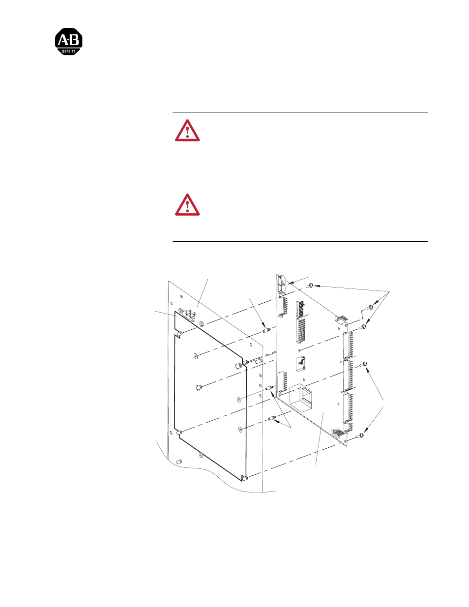
1. Install (or re-use) the three plastic spacers (p/n 179773).
2. Press the Power Interface Assembly onto the plastic spacers until fastened.
3. Fasten (and ground) the Power Interface Assembly to the Control Panel
using the five screws (p/n 179103-Q05). Torque = 0.6 to 0.7 N-m (5 to 6
in/lb).
!
ATTENTION: DC bus capacitors retain hazardous voltages
after input power has been disconnected. After disconnecting
input power, wait five (5) minutes for the DC bus capacitors to
discharge and then check the voltage with a voltmeter to ensure
that the DC bus capacitors are discharged before touching any
internal components. Failure to observe this precaution could
result in severe bodily injury or loss of life.
!
ATTENTION: Retain the insulation sheet when removing the
old Power Supply assembly. The insulation sheet must be
installed between the Power Interface assembly and the new
Power Supply assembly. Failure to follow this precaution could
result in damage to, or destruction of, the equipment.
Insulation Sheet
(Glued to Control Panel)
Control Panel
Power Interface
Assembly
➊
➊
➋
➌
➌