Publication 20p-in050a-en-p, Step 6: install the switching power supply board, Related documentation – Rockwell Automation 20P PowerFlex DC Drive - Frame D Pulse Transformer Circuit Board User Manual
Page 8
Publication 20P-IN050A-EN-P - May 2010
Copyright © 2010 Rockwell Automation. All rights reserved. Printed in USA.
www.rockwellautomation.com
Americas: Rockwell Automation, 1201 South Second Street, Milwaukee, WI 53204-2496 USA, Tel: (1) 414.382.2000, Fax: (1) 414.382.4444
Europe/Middle East/Africa: Rockwell Automation SA/NV, Vorstlaan/Boulevard du Souverain 36, 1170 Brussels, Belgium, Tel: (32) 2 663 0600, Fax: (32) 2 663 0640
Asia Pacific: Rockwell Automation, Level 14, Core F, Cyberport 3, 100 Cyberport Road, Hong Kong, Tel: (852) 2887 4788, Fax: (852) 2508 1846
Power, Control and Information Solutions
Step 6: Install the
Switching Power Supply
Board
Install the switching power supply board in reverse order of removal as
detailed in Step 3:
Remove the Switching Power Supply Board on page 4
.
Step 7: Replace the
Protective Covers and
Document the Change
1. Replace the protective covers in the reverse order of removal as
described in Step 2:
Remove the Protective Covers on page 2
2. Install DPI cable (if present).
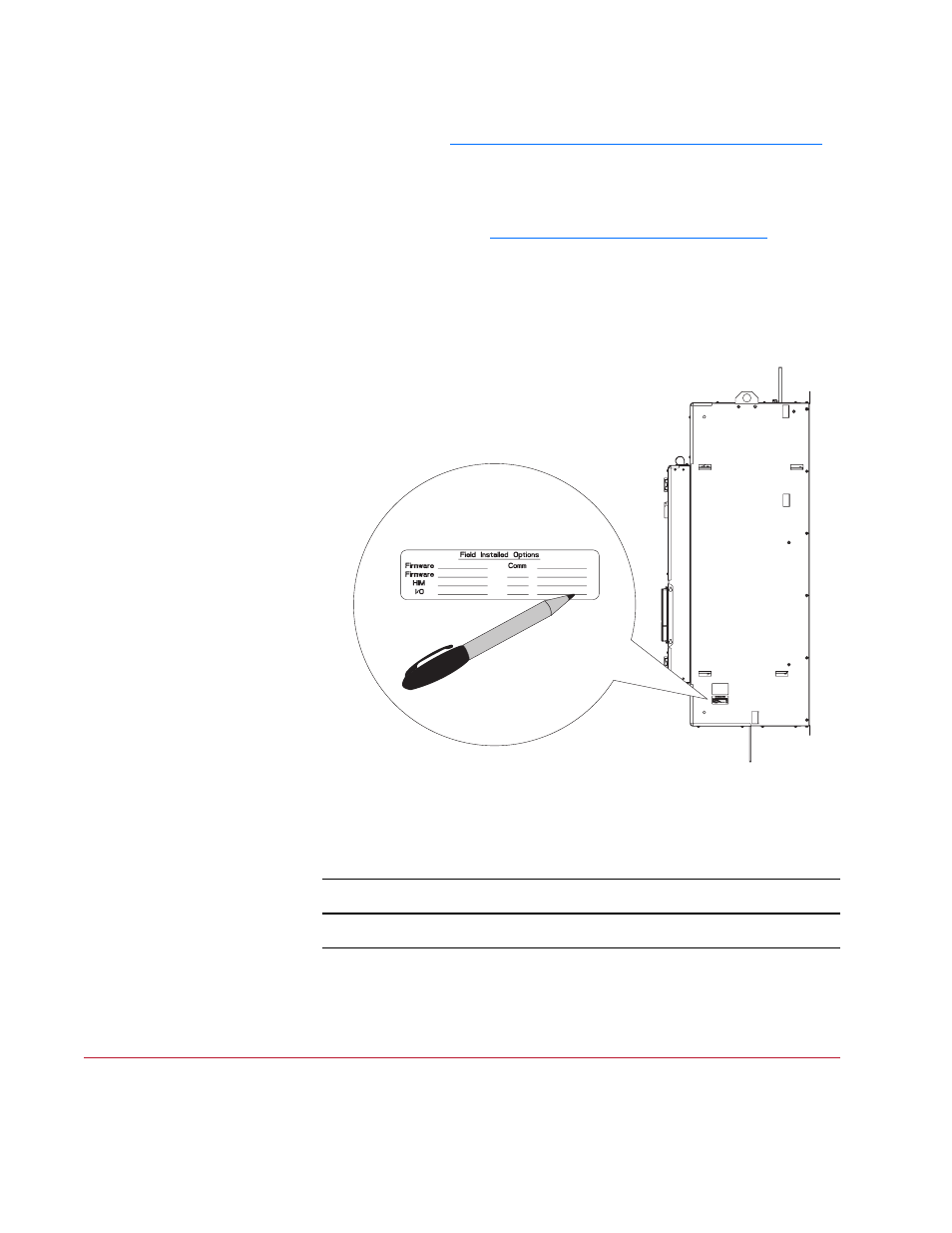
3. Record the installation of the new pulse transformer board and date of
installation on the Field Installed Option label on the side of the drive
(as shown below).
Related Documentation
Allen-Bradley publications are available on the internet at
www.rockwellautomation.com/literature
.
For . . .
Read this document
Publication
Number
In depth information regarding the
operation of PowerFlex Digital DC drives
User Manual - PowerFlex Digital DC Drives 20P-UM001…