Rockwell Automation 140G-Rx Installation Instruction-140G-R User Manual
Page 14
DIR 1000682R0002 (L5757)
(14)
8.4. Second Level maintenance operations
8.4.1. Preliminary operations:
- open the circuit-breaker and make sure that the springs of the operating mechanism are discharged.
WARNING: if work must be performed on the circuit-breakers, disconnect the power circuit and auxiliary circuits
and earth the terminals in a visible way on both the supply side and load side.
8.4.2. General inspections and cleaning:
- Check to make sure that the device (interrupting part) is clean. Remove any dust and traces of oil or grease with a clean, dry
cloth (use a mild detergent if necessary - A cleaning product such as Henkel’s 273471 or equivalent can be used if there is a
heavy coating of dirt).
- Make sure that the rating plates with the technical specifications of the apparatus are affixed
- The data plates can be cleaned with a clean, dry cloth.
- Remove all traces of dust, mould, condensation and tarnish
- Make sure that there are no traces of overheating or cracks, which could impair the isolating parts of the circuit-breaker
- Make sure that there are no foreign bodies in the circuit-breaker compartment
- Make sure that the screws that fasten the fixed part to the switchboard are well tightened (M8 - 221.3 lb-in / 25 Nm).
8.4.3. Circuit-breaker connections and connections between circuit-breaker and switchboard
- Remove any dust and dirt from the isolating parts with a brush and dry cloth (use a mild cleaning product if necessary - A
cleaning products such as Henkel’s 273471 or equivalent can be used if there is a heavy coating of dirt).
- Make sure that there are no traces of localized overheating on the terminals. This problem is denoted by the change in the
colour of the parts in contact. These parts are usually silvery in colour.
- Make sure that the bolts of the terminal connections are well tightened (M12 - 619.5 lb-in / 70 Nm).
WARNING:
if work must be performed on the circuit-breakers, disconnect the power circuit and auxiliary circuits and earth
the terminals in a visible way on both the supply side and load side.
- Make sure that the cable connecting screws are well tightened in the terminal boxes (6.19 lb-in / 0.7 Nm).
Fig. 24
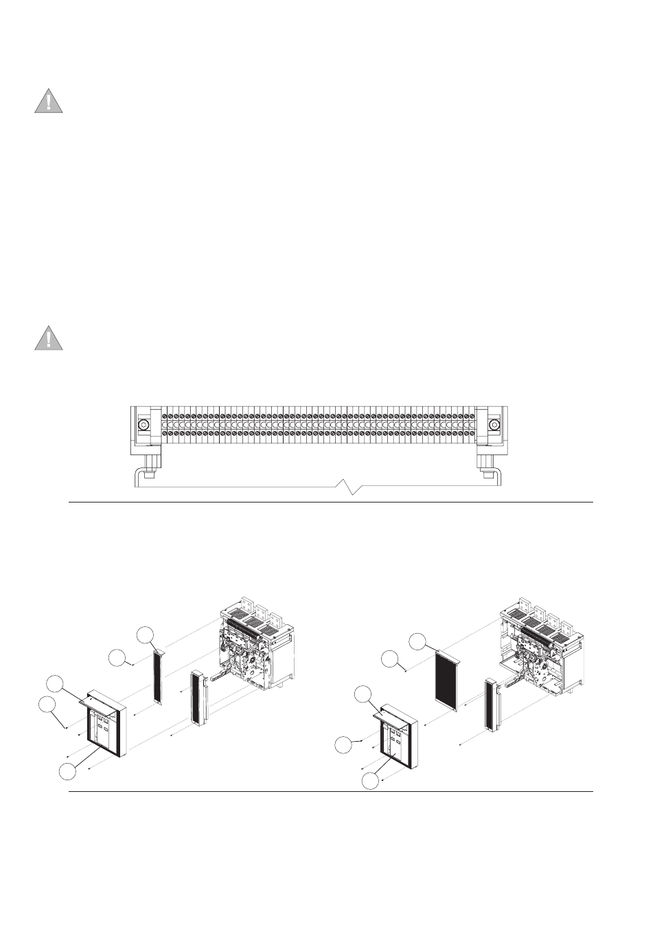
8.4.4. Flange and escutcheon plate disassembly operations
– Make sure that the circuit-breaker has been set to safe conditions as described in sect. 8.1
– Remove the flange (1) of the release as shown in figure 25.
– Remove the front escutcheon plate (2) by removing the four screws (3).
– Remove both the side guards (4) by removing the front screws (5).
Fig. 25
4
2
1
4
3
5
T8 3p
T8 4p
1
3
2
5