Mounting clearances wiring, Terminal block specifications – Rockwell Automation 20D PowerFlex 700S Auxiliary Control Power Supply User Manual
Page 2
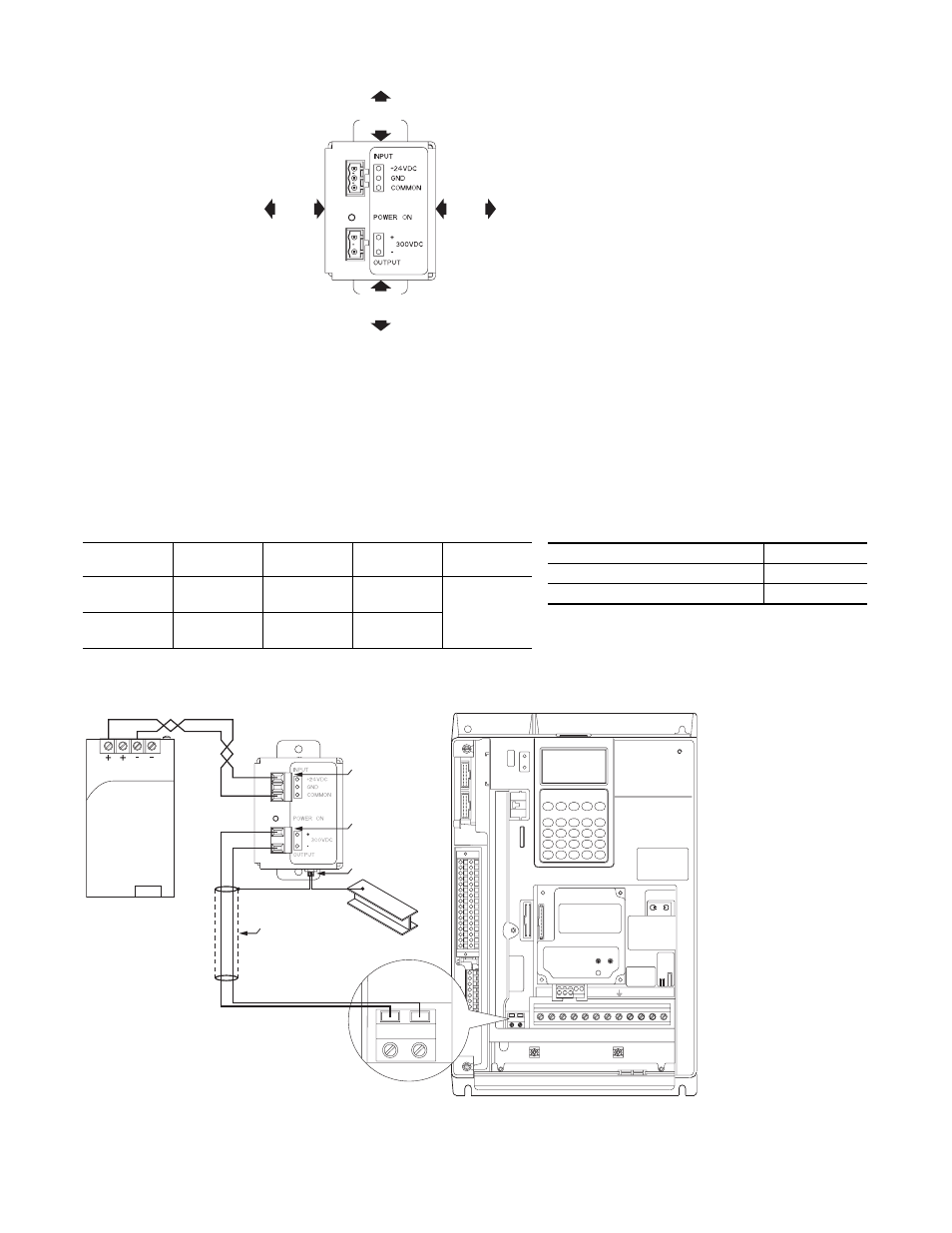
Mounting Clearances
Wiring
To meet CE installation requirements, the following wiring method must be followed.
Input Wiring – Inputs should be wired with two conductor twisted pair wire. If shielded wire is used, shields should not be
connected.
Output Wiring – Outputs should be wired using one of the following options.
A) Less than three meters of shielded two conductor wire with shield connected to ground at power supply end.
B) Three meters or less of unshielded two conductor twisted pair wire with two turns through a 1321-M001 Common
Mode Choke or equivalent. Locate choke near the power supply terminals.
Terminal Block Specifications
Note: Refer to the appropriate drive User Manual for location of the AUX Terminal Block.
Name
Maximum
Wire Size
(1)
(1) Maximum/minimum sizes that the terminal block will accept - these are not recommendations.
Minimum
Wire Size
(1)
Recommended
Wire Size
(2)
(2) Recommended sizes of 600V, 90°C wire for full load rating.
Torque
Input
Terminal Block
3.5 mm
2
(12 AWG)
0.5 mm
2
(22 AWG)
1.5 mm
2
(16 AWG)
0.4-0.5 N-m
(3.5-4.4 lb.-in.)
Output
Terminal Block
3.5 mm
2
(12 AWG)
0.12 mm
2
(26 AWG)
0.2 mm
2
(24 AWG)
50.8 mm
(2.0 in.)
50.8 mm
(2.0 in.)
50.8 mm
(2.0 in.)
50.8 mm
(2.0 in.)
Customer Supplied
24V DC
PowerFlex 700S
AUX Terminal Block
M4 Grounding Stud
Output Terminal Block
Input Terminal Block
DC 24V / 5A
BR1 B
SHLD
SHLD
V/T2 W/T3
PE R/L1 S/L2 T/L3
AUX IN+ AUX OUT–
75C Cu Wire
6 AWG [10MM
2
] Max.
12 IN. LBS.
1.4 N-M
} TORQUE
WIRE
STRIP
CONTROL
POWER
AUX IN+ AUX OUT–
Shielded Output Cable
300V DC Output Cabling Specifications
Category
Description
Insulation and Temperature Ratings
600V, 90°C
Maximum Cable Length
(1)
(1) See output wiring options above.
3 meters (9.9 feet)