With universal function base #60 0 – Rockwell Automation 40BY1 Miniature End View Transmitted Beam Control User Manual
Page 2
WIRING
All external wiring should conform to The National Electric Code
and applicable local codes. See wiring diagrams for external connec-
tions. For maximum electric shielding, rigid conduit is recommended
for extensions of scanner wiring. DO NOT RUN PHOTODETEC-
TOR WIRES AND LINE VOLTAGES IN THE SAME CONDUIT.
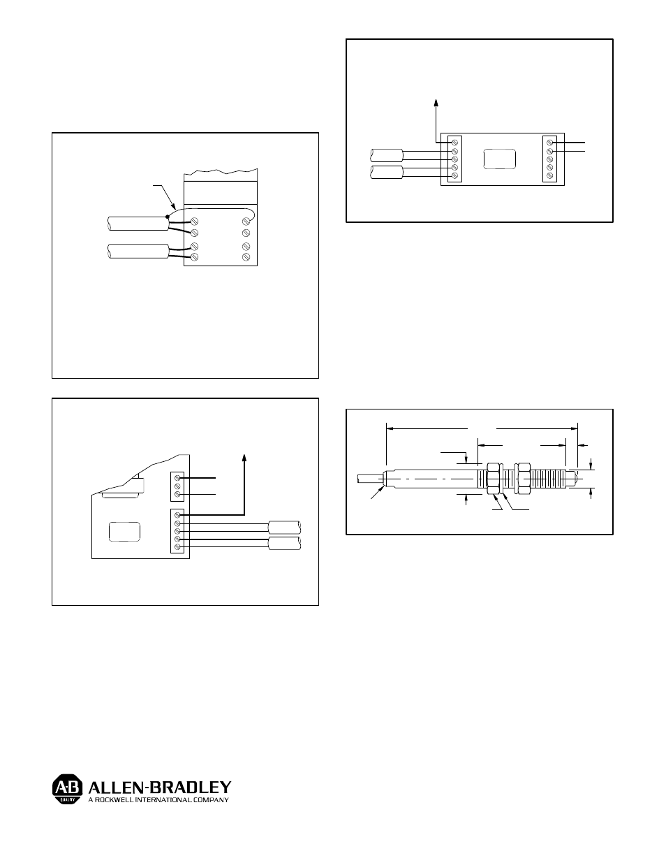
WIRING DIAGRAMS
1
2
3
4
8
7
0
5
PLUG-IN
CONTROL MODULE
SERIES 4000 LED
CONTROL BASE ONLY
BLK
RED
47BU1 RECEIVER
SHIELD WIRE SHOULD
BE INSULATED BY USER
RED
WHT
40BY1 LED SOURCE
Notes:
1. Receiver housing must always be grounded.
2. Do not ground light source shield or terminal 4.
3. Receiver housing is connected internally to its cable
shield, so shield will be automatically grounded.
4. Light source housing is not connected internally to its
cable shield. It may be grounded, but is not required.
47BU1--4000 AND 40BY1--4000
OPEN COLLECTOR (NPN) CURRENT SINK
OUTPUT TO POWER EXTERNAL LOADS
OR TO #61--2124 OUTPUT BASE
L1
L2
OUT
1
2
3
SERIES
5000
#60--2120 BASE
120VAC
RECEIVER
LED SOURCE
BLK
RED
RED
WHT
CONNECT ALL SHIELDS TO TERMINAL PS (--)
PS( --)
WITH UNIVERSAL FUNCTION BASE #60--2120
OUT
1
2
3
PS (--)
SERIES
5000
PS (+)
PS (--)
OUT
1
( + )
( -- )
24VDC
#60--2123
OPEN COLLECTOR (NPN) CURRENT SINK
OUTPUT TO POWER EXTERNAL LOADS
OR TO #61--2124 OUTPUT BASE
OUTPUT
RECEIVER
BLK
RED
#60--2123 BASE
CONNECT ALL SHIELDS TO TERMINAL PS (--)
RED
WHT
LED SOURCE
WITH MULT--MODULE FUNCTION BASE #60--2123
ALIGNMENT
Set the amplifier to the light operate mode. Adjust the sensitivity
to the maximum setting, turning the sensitivity potentiometer clock-
wise. Aim the light source at the receiver until the alignment indicator
on the amplifier turns on.
To be certain that the beam is centered, sweep the receiver at the
light source in the horizontal plane and determine the position where
the alignment indicator turns on and then off. Do the same in the verti-
cal plane. Set the beam halfway between both positions.
It may be necessary to reduce the sensitivity to a lower setting for
transparent or translucent materials or to detect objects smaller that
the effective beam.
DIMENSIONS
.38
(9.5)
ACROSS FLATS
1.85
(47.0)
.68
(17.3)
.12
(3.0)
.25
(6.35)
SWIVEL WASHER (2)
1
/
4
- 28 HEX NUT (2)
LED INDICATOR ON
40BY1 ONLY
Publication PA--9198(A)
November 1992
Supercedes Publication PA--8727