Afinia H480 3D Users Manual User Manual
Page 14
Afinia H480 3D Printer User’s Manual
14
Automatic Platform Level Calibration
To perform the Automatic Platform Level Calibration, follow these steps:
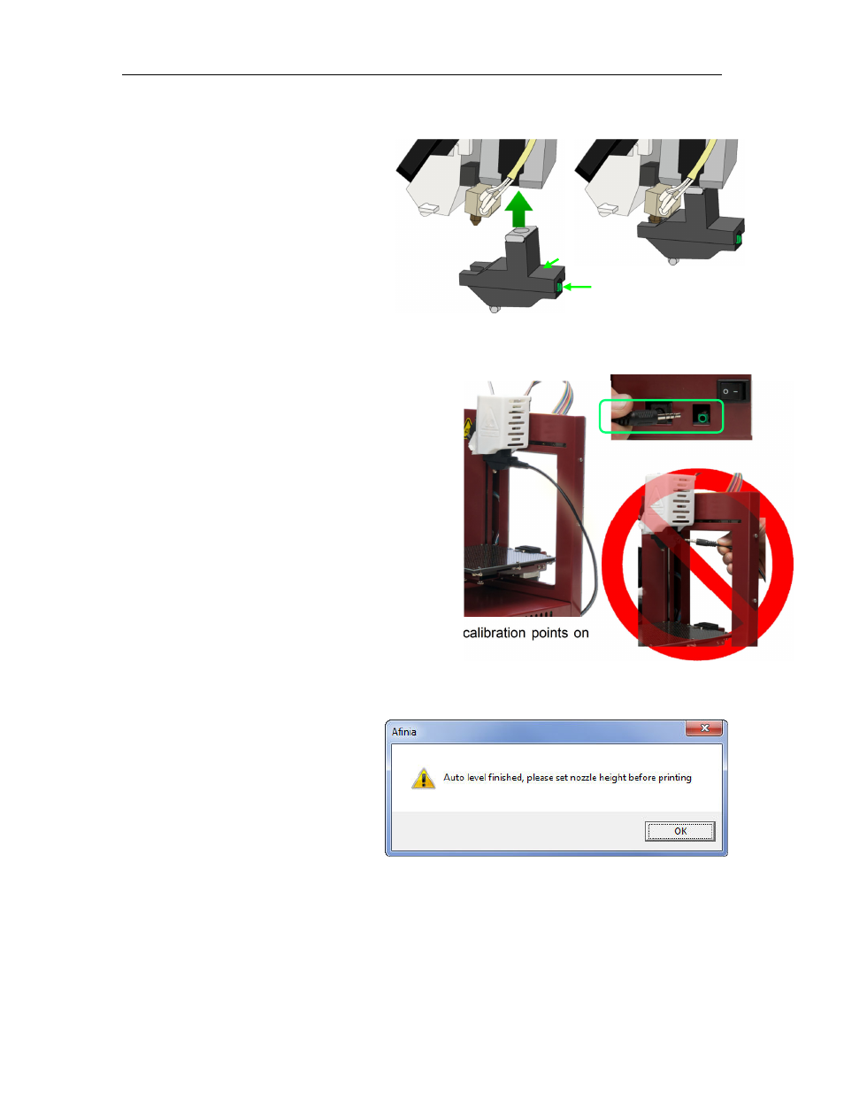
1. Attach the Platform Probe to the
bottom of the extruder.
a. Do not attach the probe if the
nozzle is above 80⁰ C!
b. Lower the platform to the bottom of
the printer by clicking the To Bottom button
in the Maintenance dialog box.
c. The magnet at the top connects to the
bottom of the Extruder Motor with the
slot for the nozzle to the left and the connection
for the data cable to the right.
d. You do not need to remove the Cover to attach the Platform Probe. The images here have
the Extruder Cover removed for clarity only.
2. Connect one end of the data cable to the data
connection n the Probe.
3. Route the cable around the right side of the
printer as shown to the right and connect the
other end of the data cable to the green data
connection on the back of the Afinia H480
printer.
NOTE: Do not attempt to pass the cable over or
through the frame of the printer, as this will
interfere with the calibration process.
4. Select Auto Level from the 3D Print menu. The
automatic process will check the height of nine calibration points on
the platform.
These heights are used to determine which of the nine points is the highest is on the
platform, and what the differences in height are between the highest point and the other
eight points.
5. The Automated Platform Level
Calibration process will reset
the nozzle height on the printer.
You will be reminded that the
nozzle height needs to be set
before printing.
6. After the Calibration is complete, remove the data cable from the Platform Probe and
disconnect the Probe from the Extruder.
7. If you wish to review the calibration values found during this process, open the Platform
Calibrate option in the 3D Print menu. Calibration values will be shown in the middle
section of that window.
Platform
Probe
Data Cable
Connection
Platform
Probe Attached