Bosch VG4-200 User Manual
Page 21
AutoDome Modular Camera System
On-Screen Display Menu Navigation | en
17
Bosch Security Systems, Inc.
VG4-200, VG4-300, VG4-500i Series User’s Manual
F01U064036 | 1.1 | 2007.01
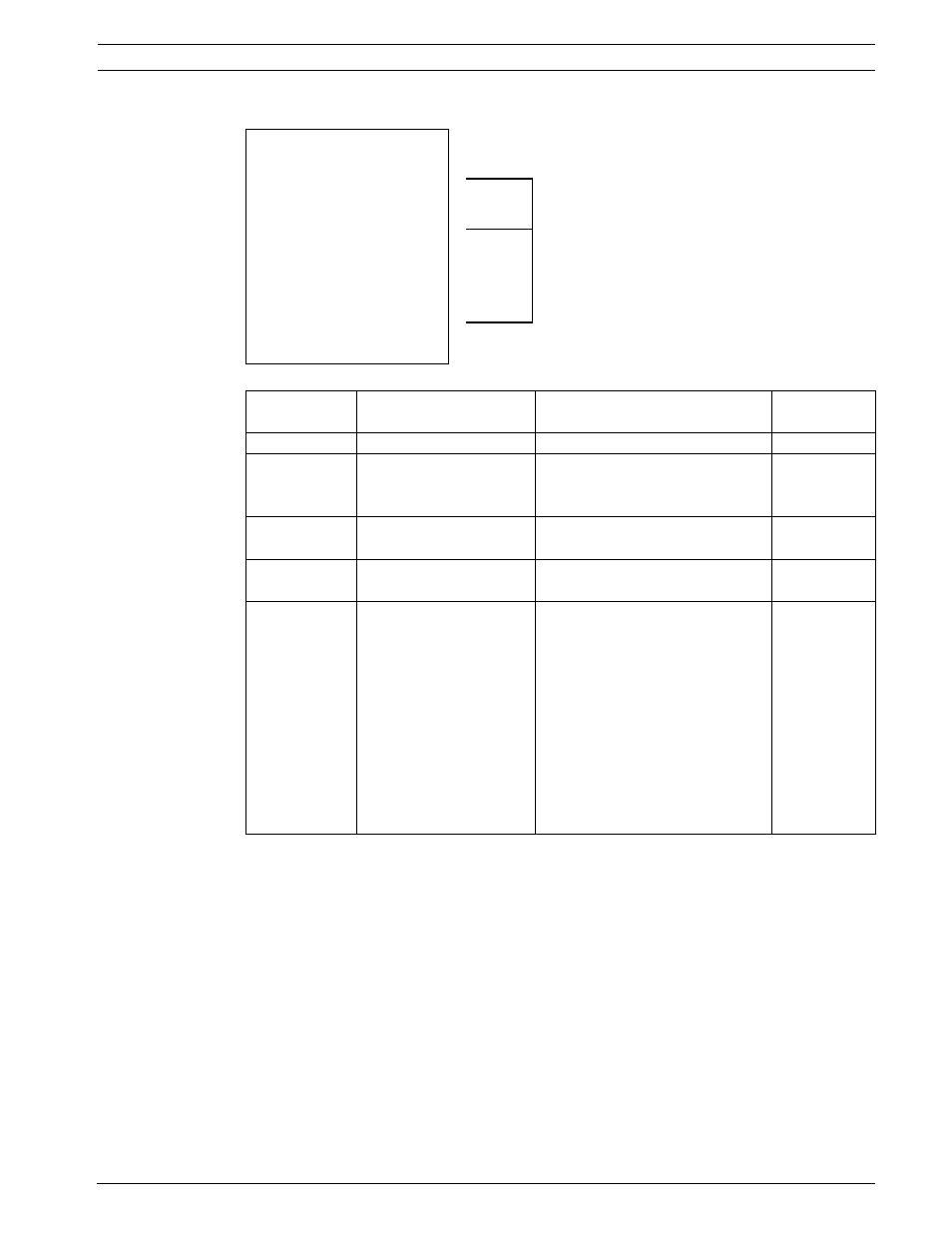
Outputs Setup Menu
Outputs Setup Menu
Outputs Setup...
Exit...
1. Alarm Output 1
N.O.
1-4
Physical
2. Alarm Output 2
N.O.
3. Alarm Output 3
N.O.
Outputs
4. Alarm Relay
N.O.
5. NONE
5-12
Command
Outputs
6. Aux On
1
7. Aux Off
8
8. Shot
99
9. OSD
10. Transmit
11. NONE
12. NONE
Focus / Iris: Select Type
Right / Left: Select Mode
Menu
Description
Sub-menu / Description
Default
Setting
Exit
Saves and exits the menu.
Outputs Setup
Defines physical outputs and
keyboard commands for use
in a rule.
Outputs 1-3
Defines a physical output.
N.O.: Normally open circuit
N.C.: Normally closed circuit
N.O.
Alarm Relay
A fixed output available for
use in a rule.
Outputs 5-12
Defines a command output for
use in a rule.
Aux On: A keyboard ON command.
Aux Off: A keyboard OFF command.
Shot: Recalls a preset shot.
OSD: An on screen display.
Transmit: Transmits a message back to
the head end (available with RS-232
serial connections, Bilinx, and IP
AutoDome models).
AutoTrack: Activates AutoTrack. (Avail-
able with 500i Series only).
NONE: No command defined.
NONE.
Outputs 5 and 6
set to
OSD and
Shot 1