WarmlyYours PD Pro Snow Switch User Manual
Page 12
Snow Switch
®
Model PD Pro
Instruction Manual
23735
Rev. B
06/14 (800) 234-4239
http: www.networketi.com
Environmental Technology, Inc.
12 of 30
POWER Cable (provided by customer)
Size for 30 Amp maximum load
SENSOR Wiring
#18 AWG jacketed, 3-conductor
HEATER Cable (provided by customer)
Size to system load
REMOTE Wiring
#22 AWG jacketed, 2-conductor
TEMPERATURE SENSOR ASSEMBLY Wiring
#22 AWG jacketed, 2-conductor
Wire Lead
Connect To:
INPUT Power
(provided by customer)
Line 1
Black
Line 2 / Neutral
White
Ground
Green
OUTPUT To Heater
(provided by customer)
Heater Load 1
Yellow
Heater Load 2
Yellow
Heater Ground (Shield)
Green
Table 2. CABLE RATINGS AND CONNECTIONS.
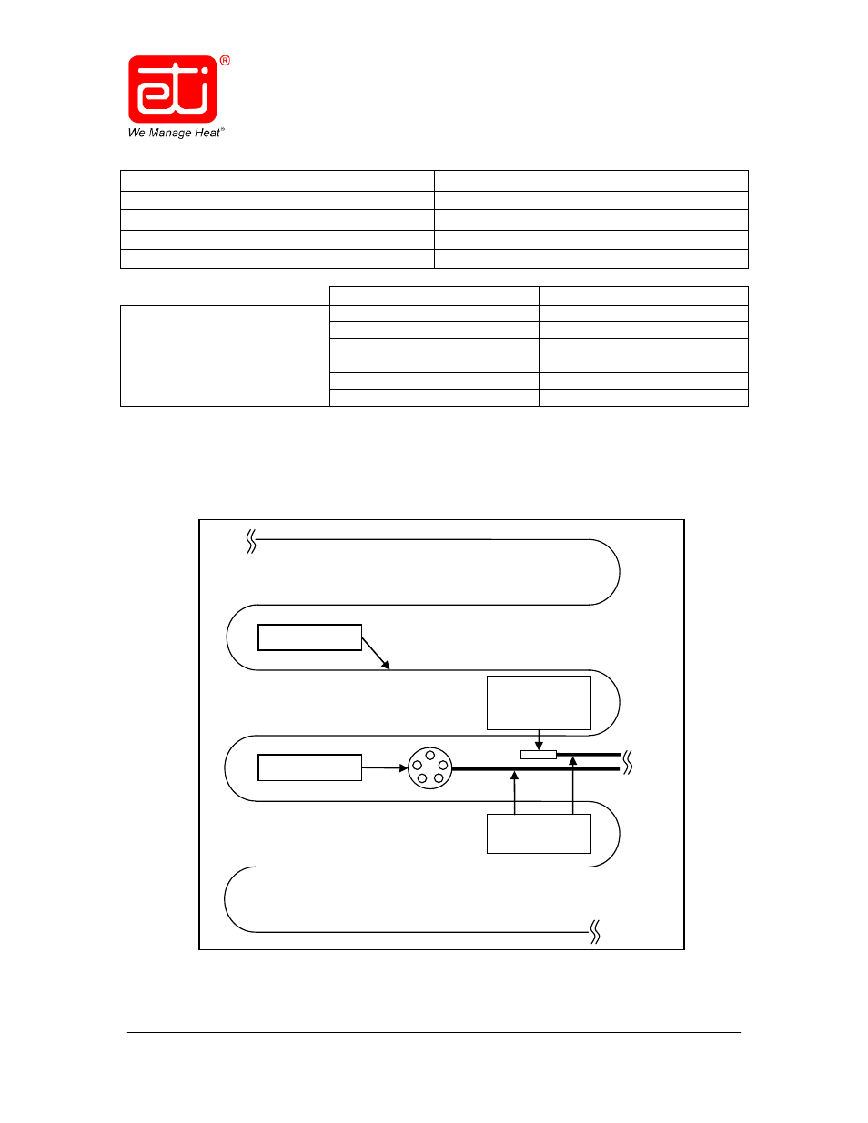
A representative schematic diagram of an SIT–6E pavement sensor installation is shown below in
Figure 3. Note how the heat tape and other components do not cross.
Figure 3. REPRESENTATIVE SIT–6E PAVEMENT INSTALLATION
SIT–6E Sensor
Heat Tape
Optional
Temperature
Sensor
(Cables Inside
Conduit)