System schematic diagrams – WarmlyYours PD Pro Snow Switch User Manual
Page 11
Snow Switch
®
Model PD Pro
Instruction Manual
23735
Rev. B
06/14 (800) 234-4239
http: www.networketi.com
Environmental Technology, Inc.
11 of 30
INSTALLING THE POWER CABLE
With the circuit breaker off, install the power cable. As shown in the wiring charts, the power
cable is provided by the customer. Size the cable for a 30 Amp maximum load. Run the cable
through conduit and connect the leads to the control box wiring. The line is black, neutral is
white, and ground is green. The unit has no power switch so remember that power is running to
the system as soon as power is applied.
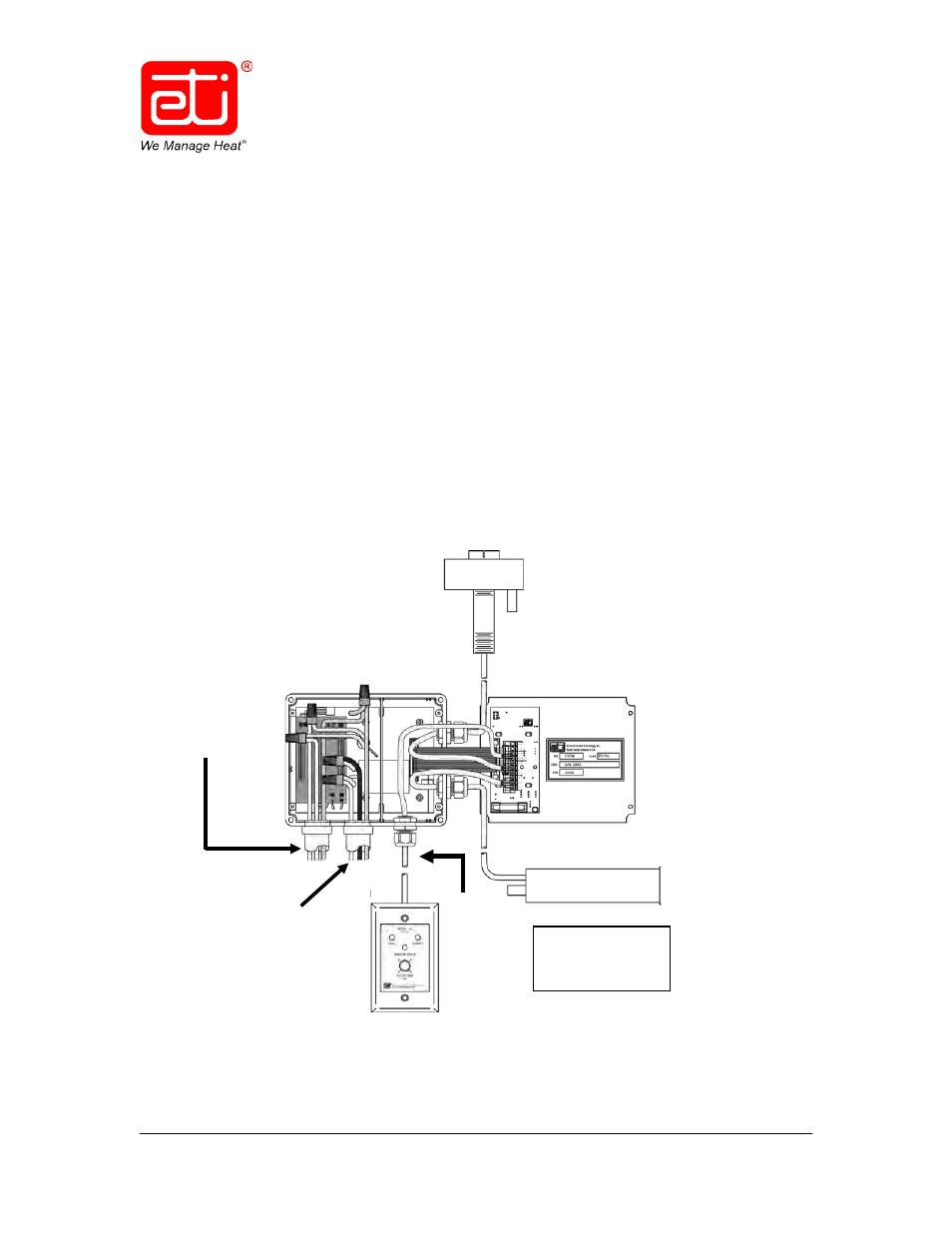
SYSTEM SCHEMATIC DIAGRAMS
This manual refers to the Snow Switch
®
Model PD Pro control panel manufactured
since October 31, 2013, which uses a universal (100 – 277 VAC; 50/60 Hz) power supply.
Older units use a voltage-specific power supply and have different wiring configurations.
Figure 2 is a schematic diagram of an entire PD Pro system, including the available optional
components.
Figure 2. REPRESENTATIVE PD Pro SYSTEM SCHEMATIC
RCU–3 &
Optional
Temp.
Sensor
(Input Power &
Ground)
CIT–1
Sensor
100 – 277 VAC
50/60 Hz
30 Amp Max.
Input Power
Line/Black
Neutral/White
Ground/Green
To Heater Cable
Heater Load 1/Yellow
Heater Load 2/Yellow
Heater Ground
(Shield)/Green
GIT–1 Sensor