WarmlyYours Snow Melting & Slab Heating User Manual
Page 3
2.0 SELECTION OF THE HEATING SYSTEM
Selection of your Heating System will depend on the application. The following can
be taken as a general guide:
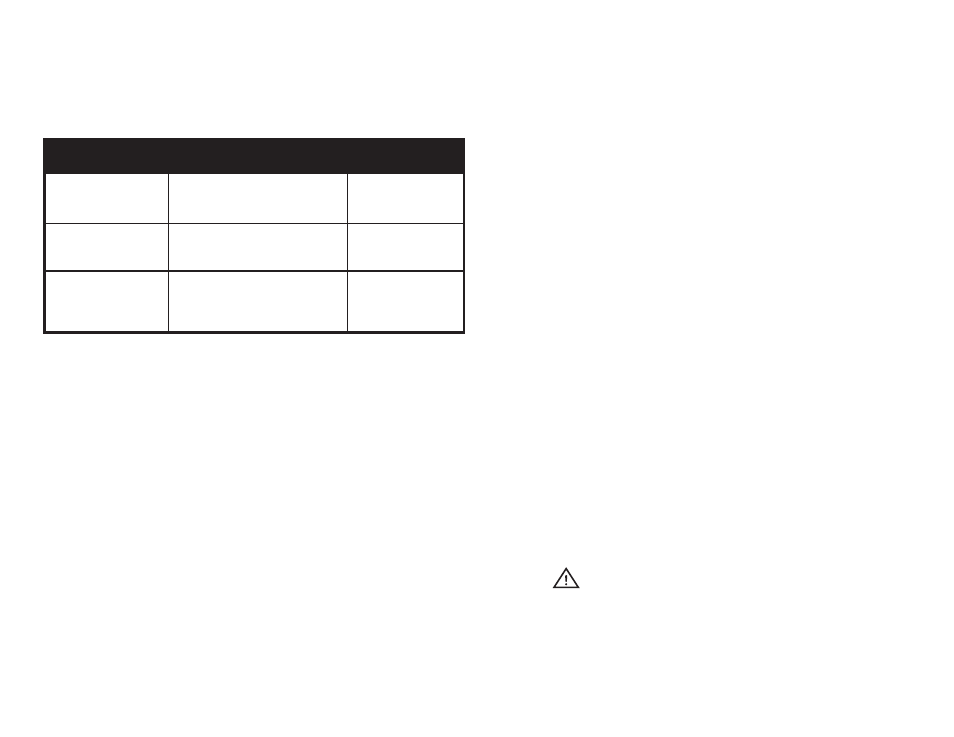
INSTALL CHART
Application
Watts per Sq.Ft. (per Sq.M.)
- Cable spacing inches (mm)
Multiplier at
given spacing
Outdoor Snow Melting
45 to 55 W/ft2 (4.18 to 5.11 W/m2)
Recommended spacing 3” (76mm).
4.0 at 3” (76mm)
Outdoor Slab Heating
25 to 35 W/ft2 (2.32 to 3.25 W/m2)
Recommended spacing 4” to 6” (102
to 152 mm).
3.0 at 4” (102mm)
2.4 at 5” (127mm)
2.0 at 6” (152mm)
Indoor Slab Heating
15 to 20 W/ft2 (1.39 to 1.86 W/m2)
Recommended spacing 7” to 10” (178
to 254mm).
1.7 at 7” (178mm)
1.5 at 8” (203mm)
1.3 at 9” (229mm)
1.2 at 10” (254mm)
Note: The heated cable spacing is mandated to generate a maximum of
15Watts/ft2 (161Watts/m2) of output in applications where a floor covering, such as
carpet, tile, or wood, is placed over the slab.
Formula: Area of Application x Multiplier at given cable spacing = Heated Cable
Length required
Example 1 (English): 100 sq.ft of Outdoor Snow Melting x 4.0 at 3” spacing = 400
feet of Heated Cable required
Example 2 (Metric): 9.3 sq.m of Outdoor Snow Melting x 4.0 at 76mm spacing =
37.2m of Heated Cable required
Please note the above-indicated values are meant as a general guide. Your values
mat vary depending on a number of factors. Please consult your Account Manager
for assistance.
3.0 IMPORTANT INSTRUCTIONS BEFORE INSTALLING THE SYSTEM
1. Heating Cable must not cross or overlap itself at any point. This could cause the
Cable to overheat, requiring replacement.
2. The Heating Cable length should not be cut or altered under any circumstances.
This may cause over heating resulting in damage to the Cable.
3. The cold lead can be cut /extended with a conventional splice, inside of an
accessible junction box (weatherproof if outdoors).
4. Take precautions to avoid damage to Heating Cable during installation. Do not
drive over cable. Duct tape the ends of shovels. Do NOT saw expansion joints,
without having lines marked off clearly with spray paint, where installer has
verified that Heating Cables will not be cut. Do NOT damage Cables with heavy
equipment, machinery or vehicles.
5. Heating Cables should be separated from other heat sources such as luminaries
and chimneys.
6. Do not install the Heating Cable below 5˚ F (-15˚ C) ambient temperature.
7. Minimum bending radius of the Heating Cable shall not be less than 10 times its
diameter.
8. Minimum spacing of Cables is 3” (76 mm) and maximum spacing of Cables is
12” (305 mm).
9. Twin Conductor Heating Cable has a ground braid (metal sheath) to be connected
to ground and 2 conductors which are to be connected to the power supply.
10. Double check the voltage and wattage of the Heating Cable received against the
project specifications on your custom installation plan. These are marked on the
packing box of the product. A qualified electrician should connect the Heating
System.
11. Check the continuity, resistance and insulation resistance of the Heating Cable
before installing and also after installing. Resistance value should match the
value shown in Appendix A on page 12. A tolerance of -5% to +10% is allowed.
Insulation resistance must be more than 10 megohms.
12. Keep high voltage power wires in a separate conduit from the low voltage wire.
13. Allow sufficient drying or curing period of the floor / slab / concrete / asphalt after
installing the Heating System and before energizing the Heating System.
14. For easy reference, fix a label at the power distribution board indicating the
location of the heating units installed.
WARNING
15. The Cable must NOT be shortened or cut in any manner or subjected to strain
at the splice joint.
16. NEVER power up Heating Cables prior to being buried in concrete, asphalt or
in mortar (even for testing purposes). This will prevent premature failure of the
Heating Cable.
2