Titus Lynergy User Manual
Page 2
2
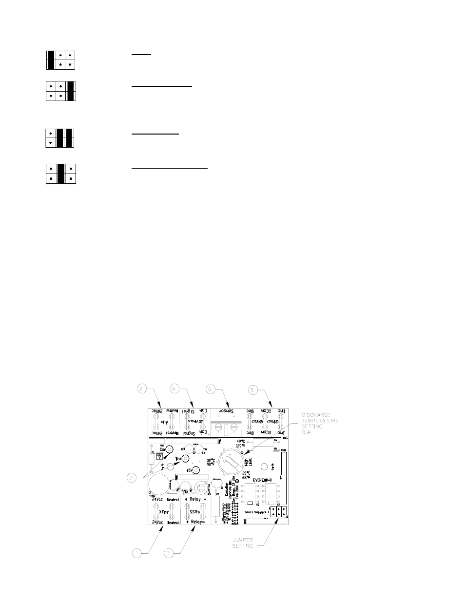
WIRING. The EHM control board is powered by 24Vac (1) from the transformer in the electric heater. The EHM has
auxiliary 24Vac outputs (2) that can be used to power the unit’s electrical controls. Next to the “Xfmr” inputs are the “+” and
“-“ Relay connections (3) that control the solid state relays by sending pulses of ~25Vdc.
There are two terminations to use for dc Volt control (4) of the electric heat (applications LX3 and LX4 from above). These
are polar sensitive. The “+” signal from the controller must be connected to “Signal” on the EHM Control Board. The “-“
from the controller must be connected to “Com” next to “Signal (Note: NOT “iCom”). A termination to “-“ is possible, but not
necessary to measure mA signals to the board.
There are three terminations for 24 Vac control (5) of the electric heat (applications LX1, LX2, LX5, LX6, and LX7 from
above). “Inc” is for the increase signal in applications LX5 and LX7, as well as the first stage heat signal in applications LX1,
LX2, and LX6. “Dec” is for the decrease signal in application LX7, as well as the second stage heat signal in applications LX2
and LX6. A connection to “iCom” is necessary for all of these 24 Vac applications. If the unit’s controller does not have a
Common output, a jumper to the correct “Aux” terminal can be used. If the unit controller outputs the “24Vac” side from it’s
input power, a jumper should be made from “Neutral” to “iCom” (See sample diagram on page 7). If the unit controller
outputs the “Neutral” side of it’s input power, a jumper should be made from “24Vac” to “iCom”.
LX4)
2-10V: This application accepts a 2-10 Vdc (4-20 mA) signal to modulate the heater
output. The output is proportional to input voltage above 2 volts (i.e., 4.5 volts sets the
heater to 25% of kW rating).
LX7)
3 Point Floating (Float): This floating input application accepts two 24 Vac inputs to
increase or decrease the heater output. As the increase signal is sent, the heater output will
increase from 0% to 100% over a 2 minute 15 second interval. If the increase signal is
removed, or decrease signal is also added, the heater output will stay constant at present
point. When only the decrease signal is received, the heater output will decline from the
present level to 0% over the same time period. This application mirrors a Three-Point
floating hot water valve.
LX5)
Incremental (Incr): This application accepts one 24 Vac input to modulate heater output.
An increase signal will increase the heater output from 0% to 100% over a 4 minute 15
second interval, staying at 100% afterward. When the signal is removed, the heater output
will decrease to 0% over the same time period. This application mirrors a Normally
Closed hot water valve.
LX6)
Bininary (Bin): This application accepts two 24 Vac inputs to step the heater from off to
33%, 67%, or 100% of the heater’s kW rating. A signal to “Inc” is 33%, a signal to “Dec”
is 67%, and a signal to both is 100%.