Replacement parts, Troubleshooting, Master / drone control parts worksheet – Titus Analog T3SQ-1 IOM User Manual
Page 4
T3SQ-1-IOM-4.0
6-6-09
All rights reserved. No part of this work may be reproduced or transmitted in any form or by any means, electronic or mechanical, including photocopying and recording, or by any information storage retrieval system without permission in writing from Air Distribution Technologies.
Note: This IOM is meant to demonstrate general dimensions of this product. The drawings on this IOM are not meant to detail every aspect of the product with exactness. Drawings are not to scale.
TITUS reserves the right to make changes without written notice.
Replacement Parts
Inlet
Size
120V Inlet Heater
6
8
10
12
0.75
1.0
1.25
1.25
kW
277V Inlet Heater
0.75
1.0
1.5
2.0
kW
Part Number
31633501
31633504
31633507
31633510
Part Number
31633503
31633506
31633509
31633512
Description
Part Number
Master Controller / Thermostat
T
3
PM - 120V/24VAC Power Module
Blue RJ-45 Power and Control Cable
White RJ-12 Power Cable
Actuator / Control Disc Assembly
Supply Air Temperature Changeover Sensor
Wiring Interface Box
Venturi Tube
Venturi Tube Guide
Control Disc Sleeve
Analog Induction Channel
Plaque / Actuator / Control Disc Assembly for T3SQ-1
18200601
31673701
31623701
31623601
31623301
31625601
31623401
72540201
72540301
72540401
31623101
31625201
Master / Drone Control Parts Worksheet
# of Master units
# of Master Controller / Thermostats
= # of Master Controller / Thermostats needed
= # of White RJ-12 Power Cables needed
# of total T
3
SQ-1 diffusers
= # of Blue RJ-45 Power and Control Cables needed
# of total T
3
SQ-1 diffusers divided by 6
= # of T
3
PM Power Modules needed – FOR NON-ELECTRIC REHEAT UNITS
This worksheet is to be used to calculate the quantity of Master Controllers / Thermostats, Cables, and Power Modules needed to
make operational T
3
SQ masters and drones. See the Wiring section of this IOM for wiring information.
# of total T
3
SQ-1 diffusers divided by 5
= # of T
3
PM Power Modules needed – FOR ELECTRIC REHEAT UNITS
OR
208V Inlet Heater
0.75
1.0
1.5
2.0
kW
Part Number
31633502
31633505
31633508
31633511
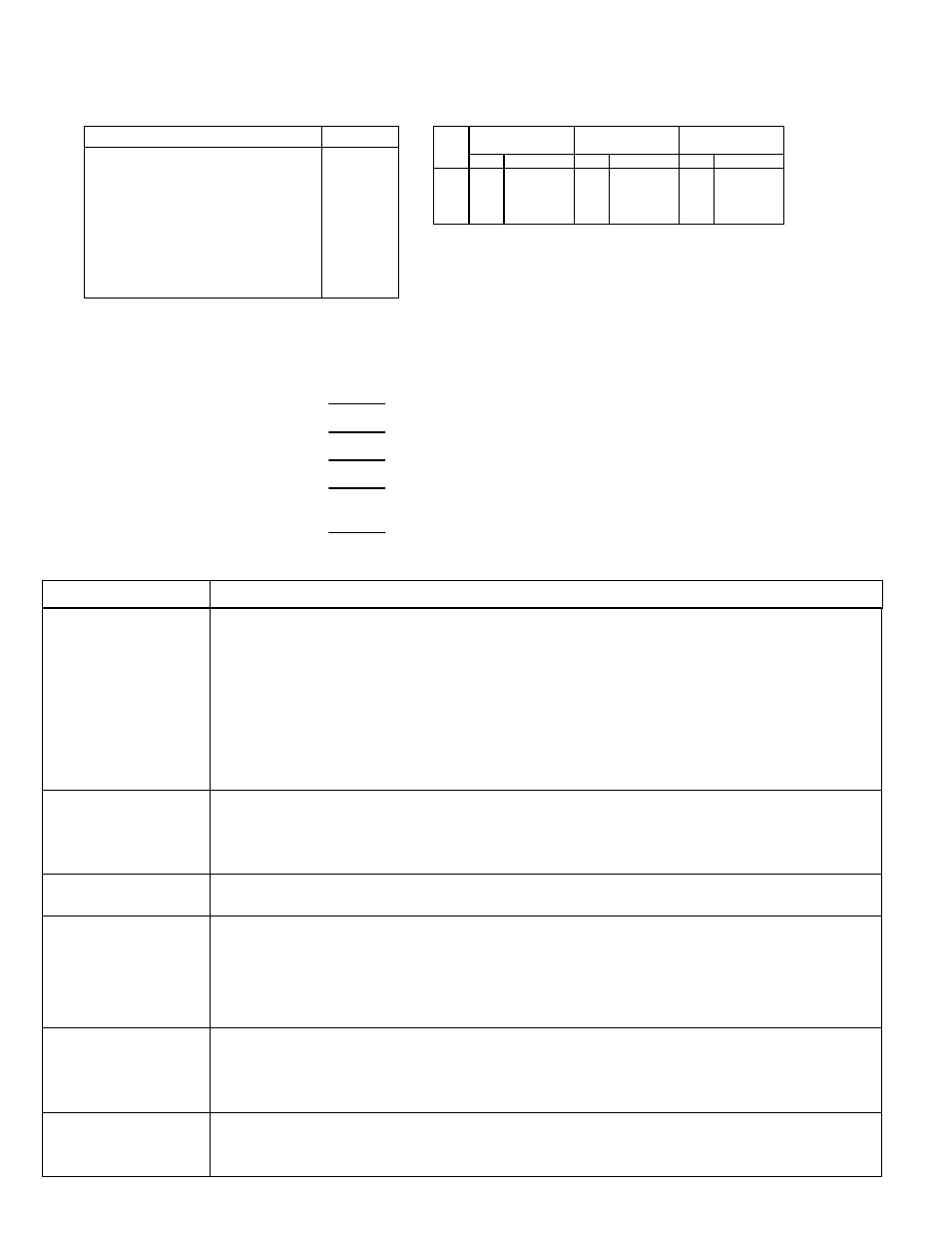
Troubleshooting
Symptom
Action
No display on master
controller / thermostat
or
Dim display on master
controller / thermostat
Verify power module wiring.
Verify cables are correct.
RJ-12, 6-pin, straight through pinout from power module to first T
3
SQ diffuser or between master T
3
SQ units
and RJ-45, 8-pin, straight through pinout from T
3
SQ diffuser to master controller / thermostat.
Verify cable continuity with a cable tester.
Note: The Power Module has integral circuit protection that protects it from shorts in the RJ-12 and RJ-45 cabling by
shutting down the Power Module. During this process, the Power Module may heat up enough that the component
coatings emit a smell much like burnt electronics, but the transformer is NOT damaged. Replace the bad cable and
cycle power to the Power Module.
Control disk will not move
Verify that control disk cable has been properly inserted through conduit and plugged into wiring interface box on
backpan.
Verify that master units is properly connected with RJ-45 to master controller / thermostat or verify that drone units are
properly connected with RJ-45 to a master unit.
Occupant uncomfortable,
control disc closed
Adjust setpoints on master controller / thermostat.
Check supply air temperature by pushing and holding top arrow for 5 seconds.
If supply air is warmer than setpoint and setpoint is below zone temperature, damper will close to reduce
supply air volume into space.
If supply air is cooler than setpoint and setpoint is above zone temperature, damper will close to reduce
supply air volume into space.
Control disk will not go to
full closed
Adjust brass nuts at the top of the actuator shaft to desired minimum position.
Supply air temperature
reading is incorrect
Verify that the supply air temperature sensor is securely connected on all master units – thermostat display will show
“00” if the supply air temperature sensor is not connected.
Verify that the supply air temperature sensor has been disconnected from all drone units – thermostat display will read
incorrectly if drone units has a supply air temperature sensor.
Unit is operating in reverse
(closing when it should be
opening, etc.)
Follow steps in “Occupant uncomfortable” above to ensure proper setpoints and verify supply air temperature.
Follow steps in “Supply air temperature reading is incorrect” above to ensure supply air temperature is correct.