Important – Schwank SEB(U) User Manual
Page 9
SP-MSEB-BX-10A
SEB Manual
RD: JUNE 2004
RL: 10
KH
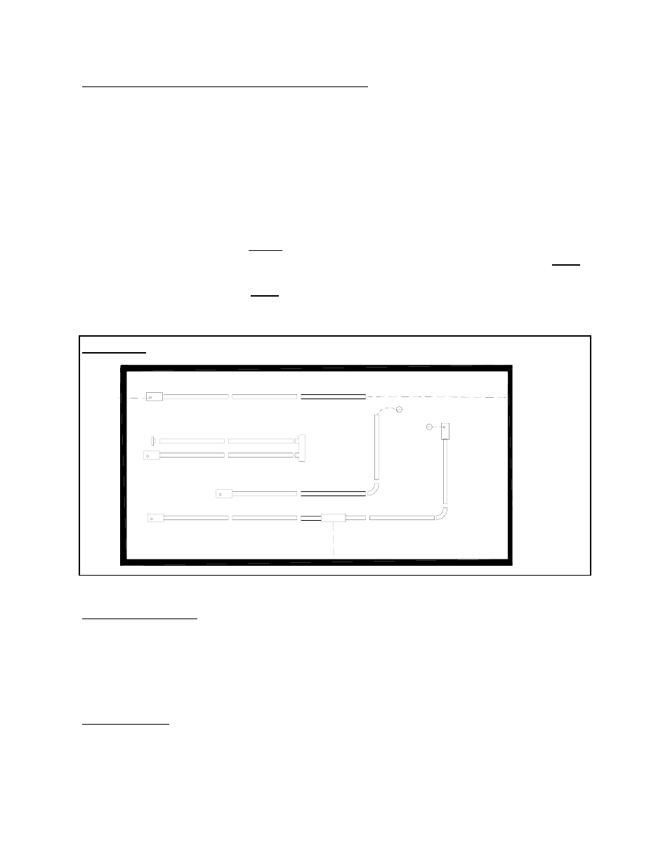
6. SYSTEMS INCORPORATING 90
O
ELBOWS
The SEB Series radiant tube heater can be in-
stalled in configurations as illustrated in Fig 2
(below) with a maximum of two 90
0
elbows
per heater. The use of radiant elbows reduces
the total maximum vent allowable. (See
Sec-
tion 10 Page 11:
Flue Venting )
The 90
0
elbows are shipped as a kit with one
tube coupler.
On Models SEB 200, 175 a minimum of
30´ of straight radiant tube must be con-
nected to the burner before any elbow. On
Models SEB 155, 130, and 110 a minimum
of 20´ of straight radiant tube must be con
FIGURE 2 SYSTEM CONFIGURATIONS
System Configuration
1 Straight line
2 “U” tube with Turn Box
3 “L” tube with 90
0
elbow kit
4 Twinned tubes into common TEE flue vent
* Note: Both heaters must be connected
with a single common thermostat
Venting Options
A Flue vent through wall 4”
B Flue vent through wall or roof 6”
C Flue vent through roof
D Flue vent into building, exhaust fan inter
locked with heater
E Combustion air intake from outside
through wall.
F Combustion air intake from outside
through roof
G Combustion air intake from inside
building
IMPORTANT:
nected to the burner before any elbow.
And on Models SEB 80 and 60, a mini-
mum of 10´ of straight radiant tube must
be connected to the burner before any el-
bows.
Page 5
B
E
A
G
4
3
G
G
D
2
1
F
C