Schwank SEB(U) User Manual
Page 12
SP-MSEB-BX-10A
SEB Manual
RD: JUNE 2004
RL: 10
KH
Page 8
8. BURNER AND TUBE INSTALLATION
With all hangers suspended at the same
height, insert first aluminized tube section,
through 4" hole into first two wire hangers.
Bolt burner to flange on first tube section,
SEE FIGURE 6 (page 7). Subsequent lengths
of tube can then be installed, by joining them
together one inside the other and locking the
joints using the aluminized steel clamp. SEE
FIGURE 7 (page 7).
Models SEB and SEBU 200 & 175 have
alumatherm as the first section with a welded
Flange, the second section is aluminized, and
subsequent lengths are steel.
Slacken the bolts and slip the coupler over
the end of the pipe to be joined, making sure
the swaged end of the tube is fully inserted
into the plain end of the tube before re-
positioning the coupler. The coupler should
then be centred across the joint before tight-
ening up. If a turbulator is necessary it will be
factory installed into the tube(s). The tube(s)
will be marked stating where it must be in-
stalled in the system, see TABLE 4 (page
10) for the models which do require turbula-
tors.
Note:
Turbulators are ALWAYS
installed at the vent end of the heater .
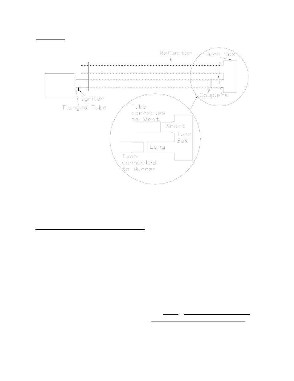
FIGURE 8 TURN BOX