Schwank SEB(U) User Manual
Page 10
SP-MSEB-BX-10A
SEB Manual
RD: JUNE 2004
RL: 10
KH
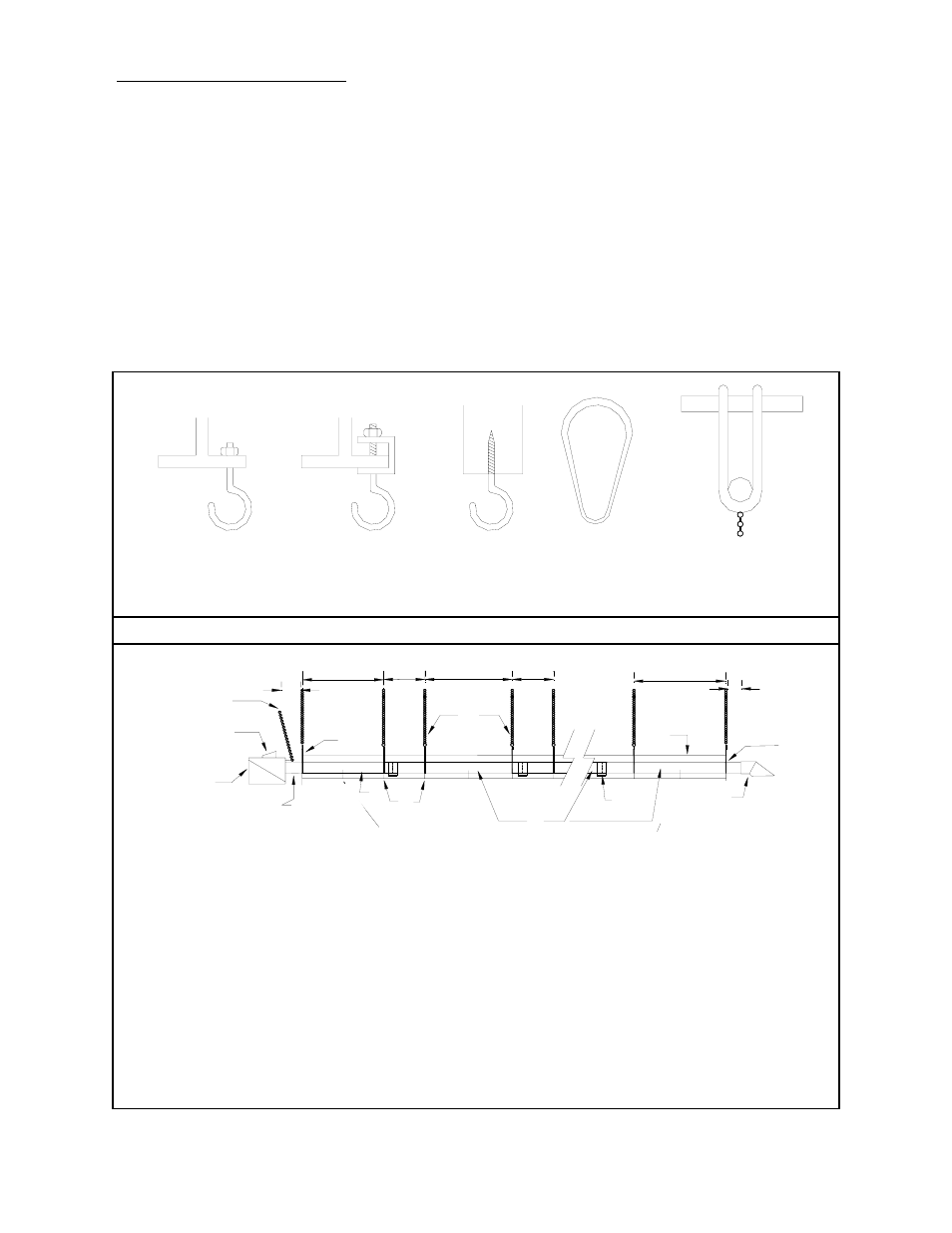
7. SUSPENSION SYSTEM
The system configuration and available
support locations must be considered in order
to locate the radiant tubes correctly. Labour
and material can be reduced by locating
(system configuration permitting) directly
under structural members such as joists, steel
or wood beams, etc.
Chain is recommended for hanging the tube
system, connecting the hangers to beam
support as illustrated in FIGURE 3 (below).
To support burner and keep it level, a
separate suspension chain must be attached
to the eye hook at flange end of burner angled
slightly back over burner, FIGURE 4
(below). This will permit normal expansion
and contraction of the tube system. (If rigid
devices such as rods are used in place of
chain, swing joints or other means of
sufficient length must be provided to
compensate for expansion.)
FIGURE 4: SEB TYPICAL HANGER & SUPPORT SPACING
Page 6
FIGURE 3: SUGGESTED MOUNTING HARDWARE
EYE BOLT THROUGH
HOLE IN BEAM
BEAM CLAMP
WITH EYE SCREW
EYE
SCREW
PIPE RING
OR CLEVIS
BAR-JOIST
CLAMP
* Distances shown are recommendations and may be varied to match field requirements.
1 Heater Support Chain
2 Burner Assembly
3 Igniter / Sensor
4 Focus Shield Reflector
5 Aluminized Tube with Flange
6 Tube Coupler
7 Steel Tube
8 Flue Vent terminal
9 Burner Support Chain
10 Wall Vent Terminal
11 Suspension Hanger
12 Gas Line
ALL TUBES MUST BE SUSPENDED BY TWO (2) HANGERS PER 10’ LENGTH, MOUNTED APPROXIMATELY 6” TO 12”
IN FROM EACH TUBE END.
10
13
2
11
4
3
5
6
8
7
9
1
1
12
3"
4"
"ALL TUBES MUST BE SUSPENDED BY TWO (2) HANGERS PER 10' LENGTH,
MOUNTED APPROXIMATELY 6" TO 12" IN FROM EACH TUBE END.